Planar support of three-dimensional mask and three-dimensional mask provided with planar support

A technology of a bracket body and a mask, applied in the field of masks, can solve the problems of long injection and cooling time of rubber material, increased production difficulty of the support frame, large space occupied by packaging and storage, etc., so as to facilitate automatic mass production and low manufacturing cost. , the effect of fast injection molding

Inactive Publication Date: 2016-11-09
北京可可考拉科技有限公司
View PDF10 Cites 6 Cited by
  • Summary
  • Abstract
  • Description
  • Claims
  • Application Information

AI Technical Summary

Problems solved by technology

The masks of these two schemes have a three-dimensional structure approximately hemispherical. The disadvantage is that the packaging and storage take up a lot of space, and the three-dimensional support frame increases the difficulty of production.
[0004] Another disadvantage of the above-mentioned three-dimensional support structure is that the manufacturing cost is relatively high
Since the thickness of the three-dimensional support frame structure reaches more than 3 to 5 cm, it is necessary to make a thicker injection mold. Compared with a thinner flat injection mold within 2 cm, the cost of the mold is higher.
At the same time, compared with a thinner injection mold, a thicker injection mold has more restrictions on the injection nozzle, the injection and cooling time of the rubber material is relatively long, and the production batch per unit time is relatively small, which restricts production. efficiency, resulting in higher production costs

Method used


Image

  • Planar support of three-dimensional mask and three-dimensional mask provided with planar support
  • Planar support of three-dimensional mask and three-dimensional mask provided with planar support
  • Planar support of three-dimensional mask and three-dimensional mask provided with planar support

Examples


Embodiment Construction

[0029] In order to have a clearer understanding of the technical features, purposes and effects of the present invention, the specific implementation manners of the present invention will now be described with reference to the accompanying drawings.

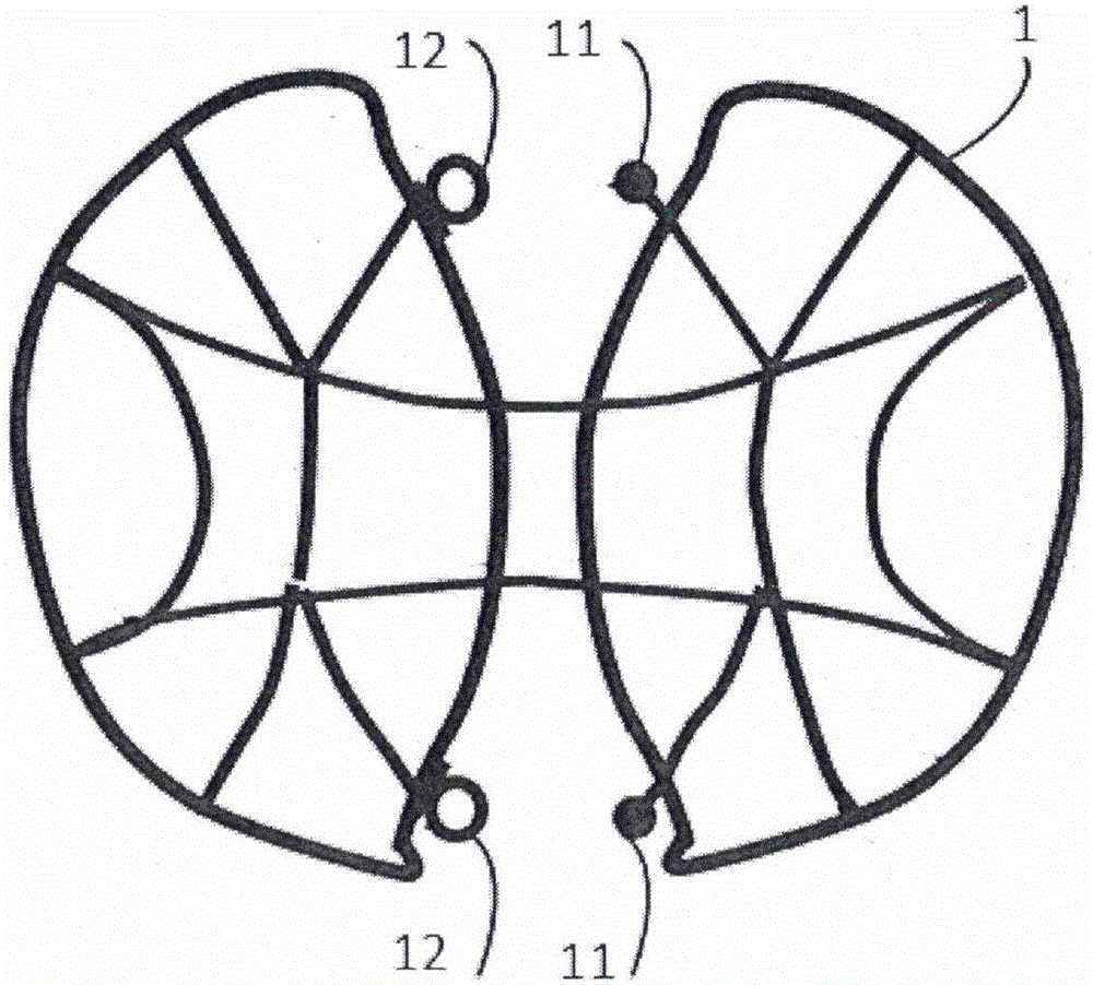
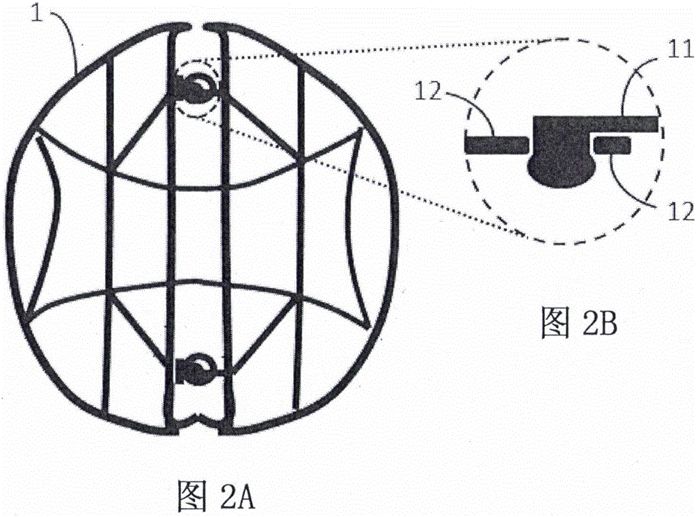
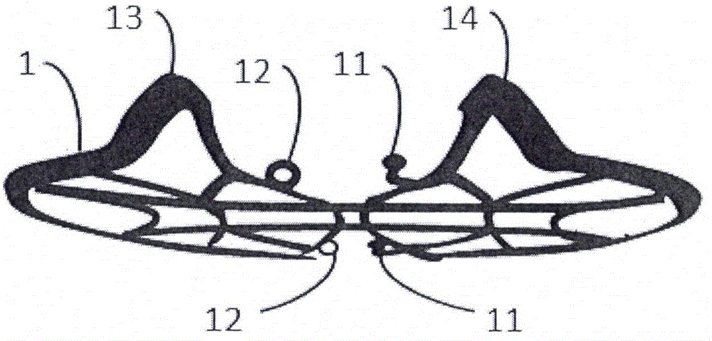
[0030] see figure 1 and Figure 2A As shown, it is a schematic diagram of the unfolded state and a schematic diagram of the structure of the connected state of a preferred embodiment of the plane three-dimensional mask bracket of the present invention. As shown in the figure, a planar three-dimensional mask support 1 of the present invention is used to be installed in the mask body 2 with a three-dimensional support space. Preferably, it is an elastic flat frame structure with mutual Two stents placed symmetrically; the adjacent sides of the two stents are the inner periphery of the stent, and the non-adjacent sides are the outer periphery of the stent; the sides of the two stents The middle position of the inner peripheral edg...


PUM


Abstract

A planar support of a three-dimensional mask is used for being mounted in a mask body provided with three-dimensional support space, adopts an elastic planar frame structure and comprises two support bodies which are symmetrically arranged, wherein adjacent side edges of the two support bodies are inner circumferential edges, and non-adjacent side edges are outer circumferential edges; a connecting body for connecting the two support bodies is arranged between the inner circumferential edges of the two support bodies, and mutually matched connectors for connecting the two support bodies are arranged on the inner circumferential edges or on inner sides of the inner circumferential edges on two sides of the connecting body; the two support bodies can bend and deform simultaneously around the connecting body towards one side surface of the planar support of the three-dimensional mask, and combine through corresponding connection by the connectors to form a three-dimensional support structure with the connecting body as the top, and outer circumferential edges of the two support bodies bend and combine to form a face attaching surface. The invention further provides the three-dimensional mask provided with the planar support. The three-dimensional mask is simple and convenient to package and store, automatic batch production is facilitated, and the three-dimensional mask producing efficiency is increased.

Description

technical field [0001] The invention relates to a mask, in particular to a plane three-dimensional mask bracket capable of being combined through flipping and a three-dimensional mask with a plane three-dimensional mask bracket. Background technique [0002] The main purpose of the mask is to isolate harmful substances transmitted by gas, such as fine particles mainly PM2.5 and viruses transmitted in aerosol state. Generally speaking, masks have a certain gas leakage rate. The corners of the wearer's mouth, chin and both sides of the bridge of the nose are the main places where leakage is likely to occur. The discontinuity of the contact surface between these areas and the mask reduces the airtight effect. One way to increase the airtight effect is to tighten the straps of the mask so that the skin of the face is sunken to achieve a seal. This way the user feels very uncomfortable to wear, and at the same time tighten the straps so that the part outside the center of the mas...

Claims


Application Information

Patent Timeline
Patent Type & Authority Applications(China)
IPC IPC(8): A41D13/11
CPCA41D13/1107A41D13/1161
Inventor 侯琰霖
Owner 北京可可考拉科技有限公司
Why Eureka
Try Eureka