Line robot drive arm with obstacle crossing function

A technology for driving arms and robots, applied in the field of robots, can solve problems such as difficult control, complex mechanical structure, complex control, etc., and achieve the effects of simple and compact structure, simple path planning, and strong operability

Active Publication Date: 2013-03-27
STATE GRID INTELLIGENCE TECH CO LTD
View PDF7 Cites 41 Cited by
  • Summary
  • Abstract
  • Description
  • Claims
  • Application Information

AI Technical Summary

Problems solved by technology

Comprehensive analysis shows that this patent mainly has the following disadvantages: when the patented robot encounters a shock-proof hammer or an insulator string, it uses the slide table at the bottom to alternate the front and rear two small arms to achieve the function of overcoming obstacles
Comprehensive analysis shows that this patent mainly has the following disadvantages: the patented walking mechanism consists of a two-section trunk and three driving claws. The two-section trunk forms a double parallelogram structure. A single motor is used to drive vertical, horizontal and telescopic, and the mechanical structure of the torso is complex and difficult to control; in the process of overcoming obstacles, it is necessary to drive the pod to adjust the center of gravity of the entire robot. This method can easily cause the robot to adjust its center of gravity Overturning occurs during the process, and the control is complicated
This patent mainly has the following disadvantages: although the method of lifting and rotating cooperation is adopted to achieve the purpose of overcoming obstacles, it has two degrees of freedom, but the rotation method adopts vertical rotation, which is different from the self-adaptive wire. When the spacing changes, the driving wheel is very prone to deflection, so that the direction of travel is no longer parallel to the direction of the wire axis, the resistance becomes larger, and the driving motor is prone to stalling

Method used


Image

  • Line robot drive arm with obstacle crossing function
  • Line robot drive arm with obstacle crossing function
  • Line robot drive arm with obstacle crossing function

Examples


Embodiment Construction

[0029] The present invention will be further described below in conjunction with the accompanying drawings and embodiments. It should be noted that the following description is only for explaining the present invention and not limiting its content.

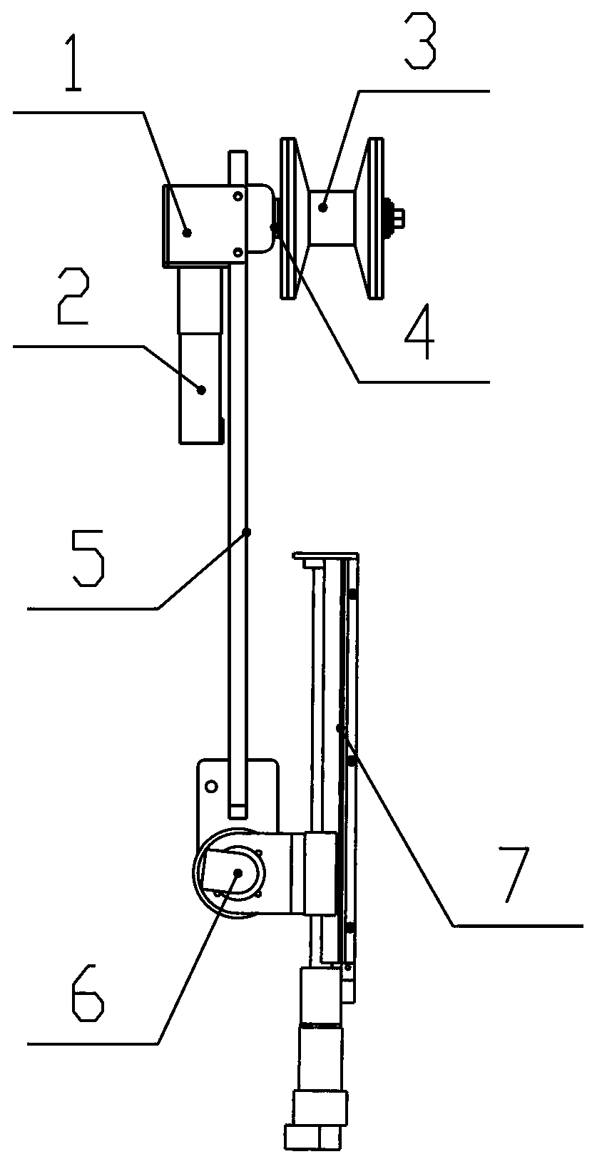
[0030] Such as figure 1As shown, the present invention includes a driving wheel mechanism, a lifting joint 7 and a rotary joint 6, and the lower end of the driving wheel mechanism is connected with the lifting joint 7 through the rotary joint 6.

[0031] The drive wheel mechanism includes a fixed plate 5, on which a drive shaft 4 is hinged, and the two ends of the drive shaft 4 are respectively provided with a drive wheel 3 and a transmission device 1, and the lower end of the transmission device 1 is fixed with a drive motor 2. The driving arm is suspended on the split wire by the driving wheel 3. The transmission device 1 is gear transmission, synchronous belt transmission or worm gear transmission.

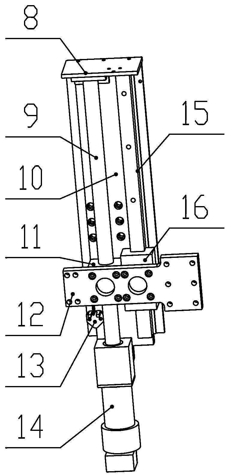
[0032] Such as figure 2...


PUM


Abstract

The invention discloses a line robot drive arm with an obstacle crossing function. The line robot drive arm is a high-voltage transmission line patrolling and operating robot drive arm and is particularly used for walking along the transmission conductor line and performing detection and operation. The line robot drive arm comprises a drive wheel mechanism, a rotary joint and a lifting joint, wherein the drive wheel mechanism comprises a fixing plate, and a drive device is movably connected onto the fixing plate. The rotary joint comprises a rotary shaft and an electromagnetic clutch, wherein the electromagnetic clutch is sleeved on the rotary shaft, and the middle of the rotary shaft is movably connected with a connecting piece. The lifting joint comprises a base plate, wherein a sliding device and a lead screw device are arranged on the base plate and are fixedly connected through a connecting plate. The drive wheel mechanism is connected with the connecting part of the rotary joint through the fixing plate, and one end of the rotary shaft of the rotary joint is connected with the connecting plate of the lifting joint. The line robot drive arm can be freely combined according to an overall structure of a robot, and each drive arm can provide drive force for the robot, is similar to modular design and is strong in interchangeability.

Description

technical field [0001] The invention relates to a robot driving arm, in particular to a line robot driving arm with the function of overcoming obstacles, in particular to a robot driving arm for walking, detecting and operating along a power transmission line. It belongs to the field of robotics. Background technique [0002] Ultra-high voltage transmission lines are an important part of high-voltage power grids. In order to ensure their safety and stability during operation, regular inspections are required; due to the distribution points of transmission lines, they are far away from towns, the terrain is complex, and the conductors are exposed to severe conditions. Leakage in the field, long-term exposure to wind and rain, and being affected by continuous mechanical tension, electrical flashing, and material aging, is likely to cause wear, broken strands, corrosion and other damage. If it is not repaired and replaced in time, it is easy to cause serious accidents and cause...

Claims


Application Information

Patent Timeline
Patent Type & Authority Applications(China)
IPC IPC(8): H02G1/02B62D57/02
Inventor 曹雷郭锐张峰仲亮
Owner STATE GRID INTELLIGENCE TECH CO LTD
Why Eureka
Try Eureka