
Ethernet-based current differential protection device and implementation method thereof

A current differential and protection device technology, applied in emergency protection circuit devices, electrical components, etc., can solve the problems of slow communication speed and high cost of communication equipment, improve protection reliability, realize regional current differential protection, and save channels The effect of construction costs

Active Publication Date: 2013-03-27
STATE GRID ZHEJIANG ELECTRIC POWER CO LTD SHAOXING POWER SUPPLY CO +2
View PDF3 Cites 10 Cited by
  • Summary
  • Abstract
  • Description
  • Claims
  • Application Information

AI Technical Summary

Problems solved by technology

The existing method is to use a dedicated fiber channel or a multiplex channel based on PDH or SDH / SONET technology, but the cost of setting up these communication devices is high and the communication rate is slow

Method used


Image

  • Ethernet-based current differential protection device and implementation method thereof
  • Ethernet-based current differential protection device and implementation method thereof
  • Ethernet-based current differential protection device and implementation method thereof

Examples


Embodiment 1

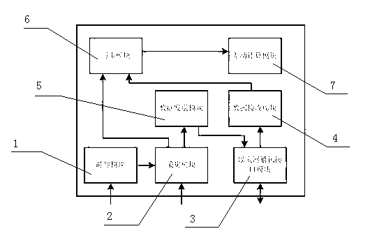
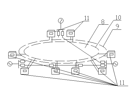
[0024] Such as figure 1 , figure 2 As shown, an Ethernet-based current differential protection device provided in this embodiment includes a clock module 1, an acquisition module 2, an Ethernet communication interface module 3, a data receiving module 4, a data sending module 5, a synchronization module 6 and Differential calculation module 7; wherein said clock module 1 is connected with acquisition module 2 through line; said acquisition module 2 is connected with synchronous module 6 and data sending module 5 through line respectively; Described data sending module 5 is connected through line Link to each other with Ethernet communication interface module 3; Described Ethernet communication interface module 3 links to each other with data receiving module 4 through line; Described data receiving module 4 links to each other with synchronization module 6 through line; Described synchronization module 6 links to each other through line It is connected with the differential ...


PUM


Abstract

The invention discloses an Ethernet-based current differential protection device and an implementation method thereof, wherein the device comprises a clock module, an acquisition module, an Ethernet communication interface module, a data receiving module, a data sending module, a synchronous module and a differential calculation module; the clock module is connected with the acquisition module through a line; the acquisition module is respectively connected with the synchronous module and the data sending module through lines; the data sending module is connected with the Ethernet communication interface module through a line; the Ethernet communication interface module is connected with the data receiving module through a line; the data receiving module is connected with the synchronous module through a line; the synchronous module is connected with the differential calculation module through a line; and the Ethernet communication interface module is in bidirectional connection with the Ethernet through a line. The differential protection device is connected with the Ethernet, and sending and receiving of sampling data between differential protections are realized by using IEC61850-9-2 standard; and the device has the characteristics of enlarging the application range of differential protection and reducing the investment cost for realizing communication service.

Description

technical field [0001] The present invention relates to electric power system relay protection, in particular to an Ethernet-based current differential protection device and its realization method. Background technique [0002] Current differential protection is widely used in transmission and distribution lines due to its superior quick action, sensitivity and selectivity. The realization of line current differential protection requires fast and reliable exchange of analog and switching values ​​between two sides of the line. The existing method is to use a dedicated optical fiber channel or a multiplex channel based on PDH or SDH / SONET technology, but the cost of setting up these communication devices is high and the communication rate is slow. [0003] Today, the rapid development of Ethernet technology is no longer limited to the application of LAN. With the development of IP services, Ethernet is gradually expanding to MAN and WAN. Ethernet has the characteristics of ...

Claims


Application Information

Patent Timeline
Patent Type & Authority Applications(China)
IPC IPC(8): H02H7/26
Inventor 朱玛金乃正钱建国徐光福张春合
Owner STATE GRID ZHEJIANG ELECTRIC POWER CO LTD SHAOXING POWER SUPPLY CO
Learn More