Light module test method

A technology for optical module testing and test items, which is applied in the field of optical communication, can solve problems such as increased production costs, waste of manpower and material resources, and reduced efficiency of optical module testing, achieving the effects of reducing production costs, improving testing efficiency, and avoiding repeated testing

Active Publication Date: 2013-03-27
SOURCE PHOTONICS CHENGDU
View PDF2 Cites 10 Cited by
  • Summary
  • Abstract
  • Description
  • Claims
  • Application Information

AI Technical Summary

Problems solved by technology

At present, during the testing process, if there are failures such as power outages, workers need to retest all optical modules, which wastes manpower and material resources, increases production costs, and greatly reduces the efficiency of optical module testing.

Method used


Image

  • Light module test method

Examples


Embodiment Construction

[0018] The present invention will be further described in detail below in conjunction with test examples and specific embodiments. However, it should not be understood that the scope of the above subject matter of the present invention is limited to the following embodiments, and all technologies realized based on the content of the present invention belong to the scope of the present invention.

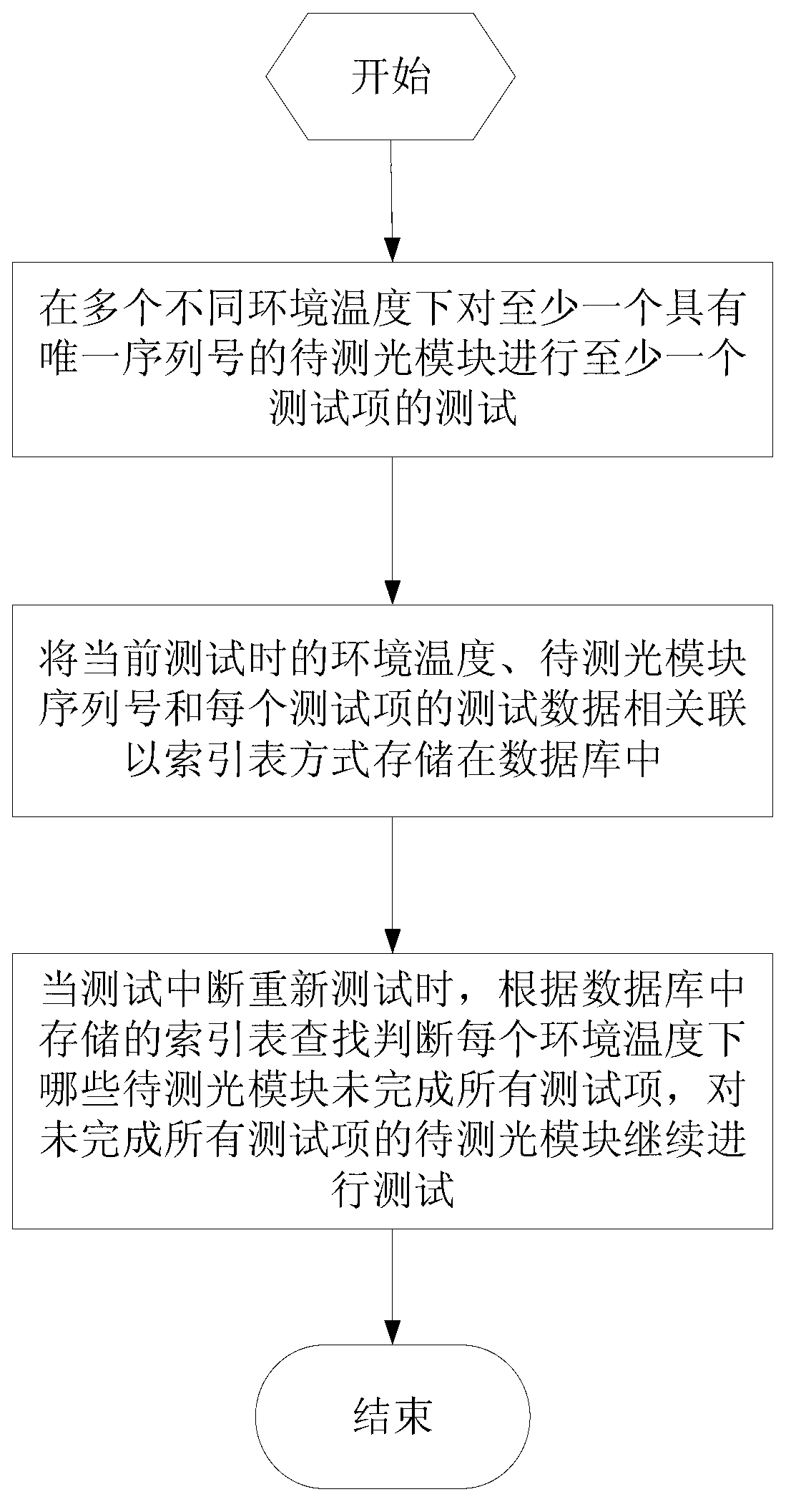
[0019] Before testing in the present invention, multiple optical modules to be tested are installed on the test board, and multiple optical modules to be tested are connected to various testing instruments through the test board, such as optical power meter (test optical power), oscilloscope (test optical eye diagram) , Attenuator (test sensitivity, overload, optical power loss, etc.), etc. The test host is connected to the test board bus, the test board with multiple optical modules to be tested is placed in the incubator, the test host controls the temperature of the incubator, and...


PUM


Abstract

The invention discloses a light module test method which includes the following steps: conducting test of at least one test item on at least one light module to be tested and with unique serial number under multiple different environment temperatures, correlating environment temperature, serial number of the light module to be detected and test data of each test item in current test, storing the data in a local database in index table mode, enabling the test data of each test item to utilize the serial number of the light module to be tested as index and the serial number of the light module to be tested to utilize the environment temperature as index, searching and judging which light modules to be tested under each environment do not finish all test items according to an index table stored in the local database and continue testing on the light modules to be tested and not finishing all the test items when the test is suspended and restarted. The light module test method does not require testing the light modules finishing all tests, avoids repeated test and improves test efficiency.

Description

Technical field [0001] The invention involves the field of optical communication technology and specially involves a test method of light module. Background technique [0002] In the process of production and communication optical modules, various performance parameters need to be performed on the optical module, such as testing of optical power, receiving optical power, and optical diagram of the optical module.Before the test, install multiple light modules on the test board. The light module located on the test board connects to various optical road test instruments through multiple light switches.carry out testing.During the test process, if there are faults such as power outages, workers need to re -test all the light modules, waste human resources, increase production costs, and reduce the efficiency of optical modules. Invention content [0003] The purpose of the present invention is to overcome the above deficiencies in the existing technology, and provide a test method...

Claims


Application Information

Patent Timeline
Patent Type & Authority Applications(China)
IPC IPC(8): H04B10/07
Inventor 古颖泉陈晓鹏胡云克瑞斯·劳鲍特
Owner SOURCE PHOTONICS CHENGDU
Why Eureka
Try Eureka