Step type valve

A stepped, valve technology, applied in the direction of lift valve, valve device, engine components, etc., can solve the problem of difficult application of high temperature fluid, valve seat leakage, etc., to achieve the effect of suppressing the rising flow, reducing the gap, and not easy to flow

Active Publication Date: 2013-03-27
MITSUBISHI ELECTRIC CORP
View PDF9 Cites 3 Cited by
  • Summary
  • Abstract
  • Description
  • Claims
  • Application Information

AI Technical Summary

Problems solved by technology

However, if the clearance is ensured in advance, the valve stretches longest when the gas temperature is at the highest temperature. Therefore, there is a clearance not only at normal temperature but also in the temperature range lower than the highest temperature, and the valve seat will be generated at this time. leakage
In this way, there is a tradeoff relationship between suppressing seat leakage and avoiding valve seizure, so it is difficult to apply to high temperature fluids

Method used


Image

  • Step type valve
  • Step type valve
  • Step type valve

Examples


Embodiment approach 1

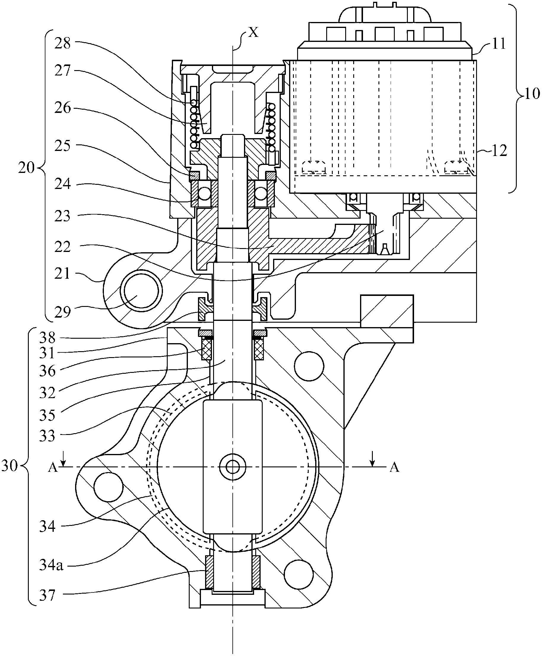
[0021] figure 1 The stepped butterfly valve shown is composed of an actuator portion 10, a gear portion 20, and a valve portion 30. The actuator portion 10 generates a rotational driving force for opening and closing the valve, and the gear portion 20 connects the actuator portion The driving force of 10 is transmitted to the valve shaft 32. The valve portion 30 is provided in a pipe (not shown) through which fluid such as high-temperature gas flows, and opens and closes the valve 33 to control the flow rate of the fluid.

[0022] The actuator section 10 uses a DC motor or the like for the electric motor 11 and covers the electric motor 11 with a heat shield 12. One end of the output shaft of the electric motor 11 is a pinion gear 22 that extends into the gear box 21. When the electric motor 11 is driven forward or reversely, the pinion gear 22 meshes with the gear 23 and rotates, thereby transmitting the driving force of the electric motor 11 to the valve shaft 32. The valve sh...


PUM


Abstract

The shape of a valve (33) is a deformed circle such that the diameter in a direction perpendicularly intersecting a pertinent axis, which is a direction that perpendicularly intersects a rotation center axis (X), is longer than the diameter in the direction of an axis parallel to the rotation center axis (X). The front surface of a semicircle on one side of the rotation center axis (X) and the back surface of a semicircle on the other side of the rotation center axis (X) abut a valve seat (34a).

Description

Technical field [0001] The present invention relates to a stepped valve in which the valve abuts a step (step) provided in a fluid passage. Background technique [0002] Conventional butterfly valves have a structure in which an elliptical valve directly abuts the fluid passage obliquely (for example, refer to Patent Documents 1 to 4), and a stepped type in which a circular valve abuts a step (step) provided in the fluid passage Valve structure, etc. [0003] In the case of a structure in which an elliptical valve directly abuts the fluid passage obliquely, compared to a stepped valve structure in which a circular valve and a stepped portion provided in the fluid passage abut, even when the valve starts to open The same valve opening can also reduce the opening width between the valve and the passage, thereby suppressing the rising flow. However, it is necessary to obliquely process the outer peripheral surface of the valve so that the elliptical outer peripheral surface of the v...

Claims


Application Information

Patent Timeline
Patent Type & Authority Applications(China)
IPC IPC(8): F16K1/22F16K1/42
CPCF16K1/222F16K1/226
Inventor 高井克典横山雅之长谷川晓
Owner MITSUBISHI ELECTRIC CORP
Why Eureka
Try Eureka