Door panel structure and method of producing the same

a door panel and door panel technology, applied in the direction of doors, roofs, monocoque constructions, etc., can solve the problems of increasing production costs and deteriorating durability of molding dies, and achieve the effects of reducing the opening width of weather strips, increasing durability of molding dies, and enhancing strength of molding dies

Active Publication Date: 2008-03-27
NISSAN MOTOR CO LTD
View PDF0 Cites 2 Cited by
  • Summary
  • Abstract
  • Description
  • Claims
  • Application Information

AI Technical Summary

Benefits of technology

[0013]In the door panel structure according to an embodiment of the present invention, upper end peripheries of the door panel and the door waist reinforcement at the door waist are substantially spaced apart from each other. Therefore, a weather strip that is fitted to the substantially spaced upper end peripheries of the door panel and the door waist reinforcement can be formed such that the opening width of the weather strip is increased corresponding to the spacing between the upper end peripheries of the door panel and the door waist reinforcement. This results in dispensing with a molding die having a narrow die head corresponding to the opening width of the weather strip upon producing the weather strip. Therefore, the strength of the molding die can be enhanced to thereby increase durability of the molding die. Further, the work of reducing the opening width of the weather strip can be eliminated to thereby reduce the production cost and enhance the fitting accuracy of the weather strip with respect to the upper end peripheries of the door panel and the door waist reinforcement.

Problems solved by technology

This results in deterioration in durability of the molding die.
Since, the work of reducing the opening width of the weather strip so as to adapt to the thin thickness of the waist flange is conducted after forming the weather strip as described above, the work efficiency is deteriorated to thereby cause an increase in the production cost.

Method used


Image

  • Door panel structure and method of producing the same
  • Door panel structure and method of producing the same
  • Door panel structure and method of producing the same

Examples


first embodiment

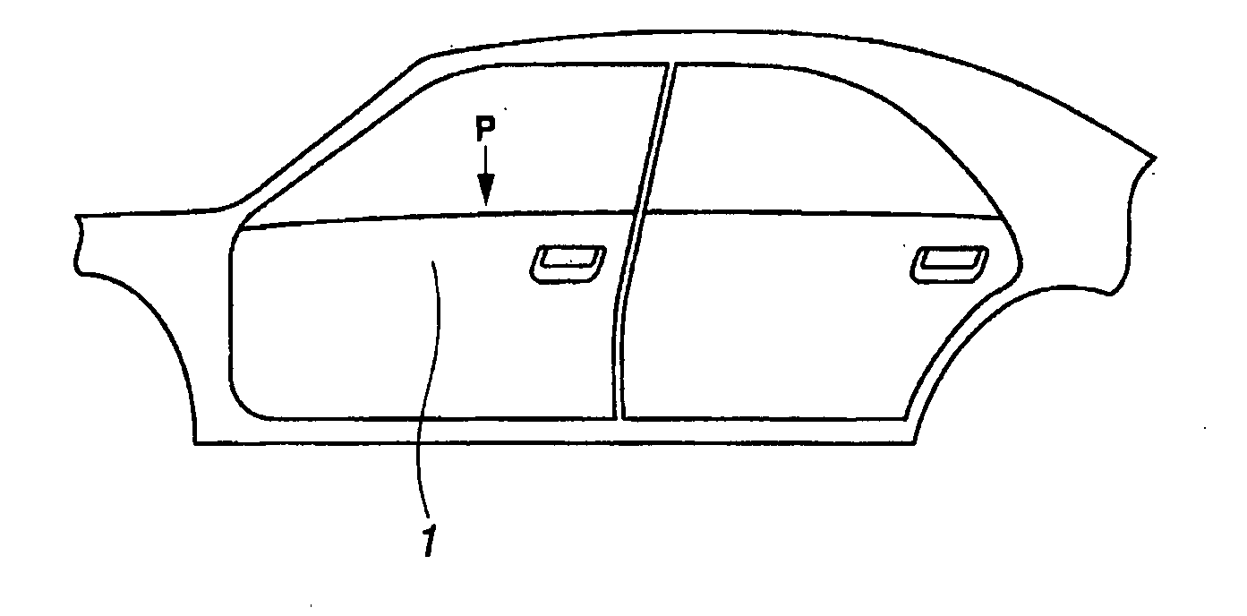
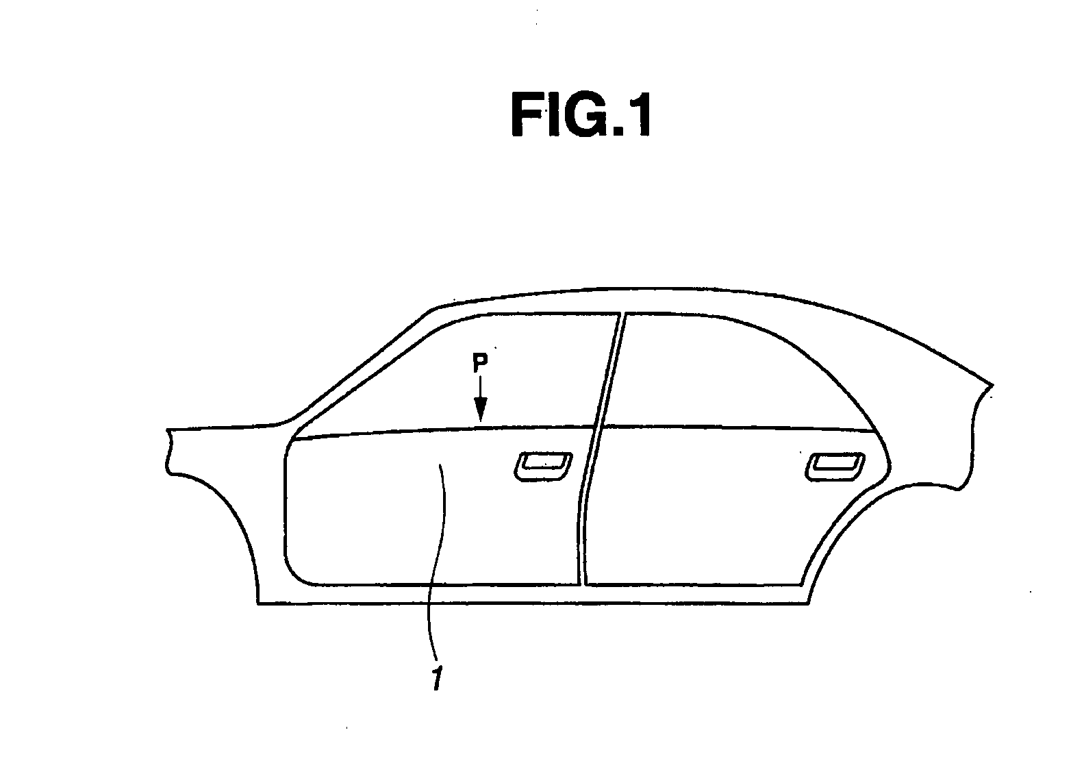
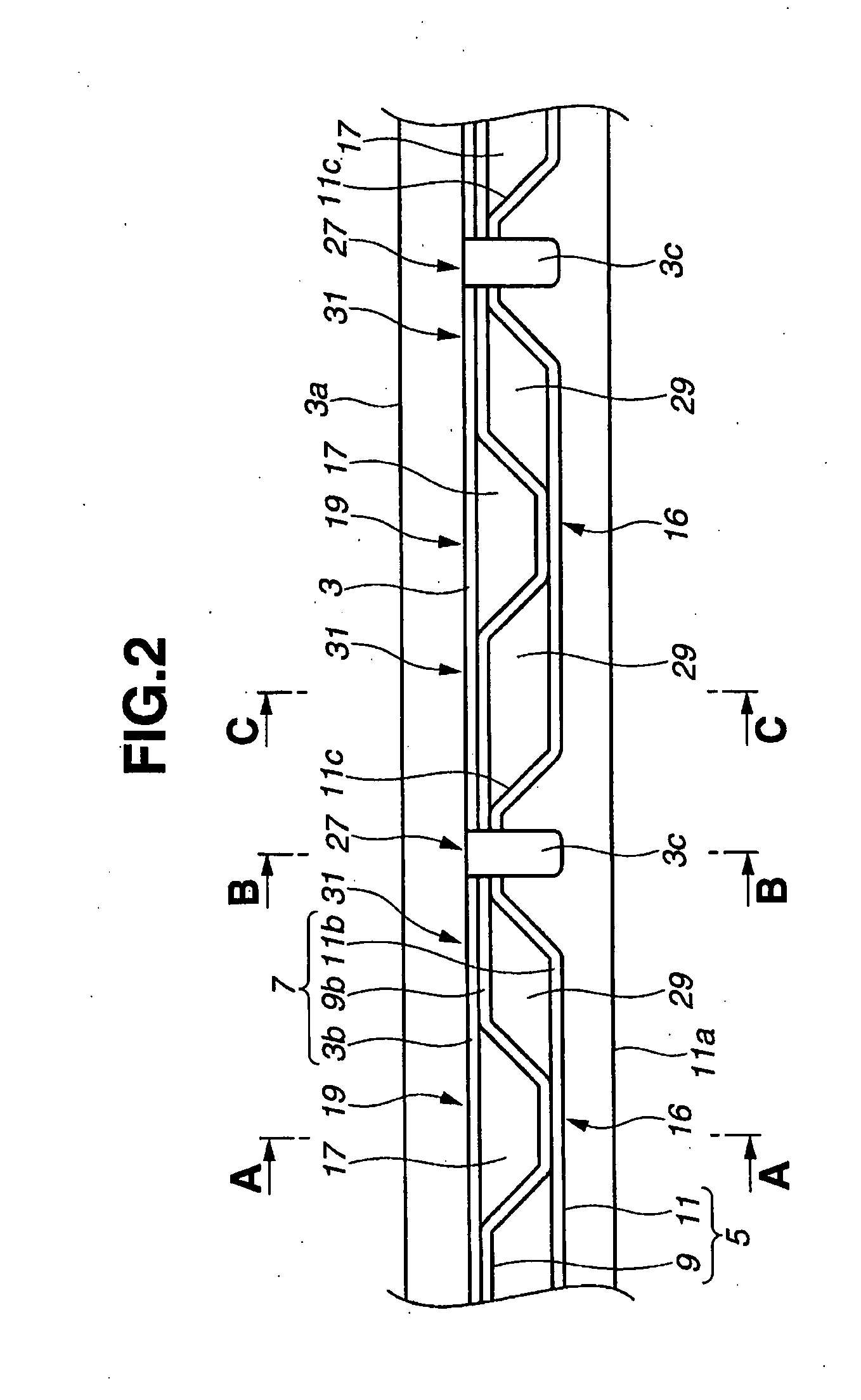
[0027]FIG. 1 is side view of a part of an automobile to which a door panel structure of the invention is applied. FIG. 2 is a plan view of waist flange 7 of the door panel structure at door waist 1 of the automobile as shown in FIG. 1, when viewed from a direction of arrow P shown in FIG. 1. Waist flange 7 includes door panel 3 (i.e. inner panel) and door waist reinforcement 5 at door waist 1.

[0028]FIG. 3A is a cross section taken along line A-A of FIG. 2, FIG. 3B is a cross section taken along line B-B of FIG. 2, and FIG. 3C is a cross section taken along line C-C of FIG. 2. An up-and-down direction in FIGS. 3A-3C indicates a vertical direction of the automobile.

[0029]Door waist 1 of the automobile includes door panel 3 having projecting portion 3a as shown in FIGS. 3A-3C. Projecting portion 3a projects toward an inside of the automobile body and extends over a length of the automobile in a fore-and-aft direction of the automobile body (in a direction perpendicular to a paper surfa...

second embodiment

[0062]FIG. 6 is a plan view of the door panel structure of the present invention. FIG. 7 is a cross section similar to FIG. 3B, but showing the cross section taken along line D-D of FIG. 6.

[0063]In the second embodiment, connecting portion 27 of FIG. 1 is modified as indicated at connecting portion 27A. Specifically, in the first embodiment, at waist flange 7 (flanges 3b, 9b and 11b) shown in FIG. 2, door panel 3 is in the form of a flat plate shape without projections and recesses in the fore-and-aft direction of the automobile body (i.e. in the right-and-left direction in FIG. 2). In contrast, in the second embodiment, inner reinforcement 9 and outer reinforcement 11 are in the form of a flat plate shape without projections and recesses in the fore-and-aft direction of the automobile body.

[0064]Further, similar to the first embodiment, flange connecting portion 16A is formed by connecting and fixing flat-plate shaped flanges 9b and 11b of inner and outer reinforcements 9 and 11 to...


PUM


Abstract

A door panel structure including a door panel and a door waist reinforcement connected to the door panel. The door waist reinforcement includes an inner reinforcement and an outer reinforcement. The door panel and the door waist reinforcement have respective upper end portions which form a waist flange to which a weather strip is fitted. The waist flange includes a plurality of connecting portions at which the upper end portion of the door panel and the upper end portion of the door waist reinforcement are connected to each other, and at least one spaced portion at which the upper end portion of the door panel and the upper end portion of the door waist reinforcement are spaced from each other.

Description

CROSS-REFERENCE TO RELATED APPLICATIONS[0001]This application claims priority under 35 U.S.C. §119 to Japanese Patent Application No. 2006-260355, filed on Sep. 26, 2006, the disclosure of which is incorporated by reference herein in its entirety.BACKGROUND OF THE INVENTION[0002]1. Field of the Invention[0003]The present invention relates to a door panel structure for an automobile, in which a weather strip is fitted to an end periphery of a door panel and an end periphery of a door waist reinforcement at a door waist of the automobile, and relates to a method of producing the door panel structure.[0004]2. Description of Related Art[0005]A conventional door panel structure for an automobile includes a waist flange that corresponds to an end periphery of a door panel and an end periphery of a door waist reinforcement which are joined with each other at a door waist of the automobile. A weather strip having a generally U-shaped section is fitted to the door waist flange from an upper ...

Claims


Application Information

Patent Timeline
Patent Type & Authority Applications(United States)
IPC IPC(8): B60J5/00
CPCB60J5/0411B60J5/0426B60J10/041B60J5/0447B60J5/0437B60J10/75
Inventor KAMEOKA, HIDENORI
Owner NISSAN MOTOR CO LTD
Why Eureka
Try Eureka