Door panel structure and method of producing the same
a door panel and door panel technology, applied in the direction of doors, roofs, monocoque constructions, etc., can solve the problems of increasing production costs and deteriorating durability of molding dies, and achieve the effects of reducing the opening width of weather strips, increasing durability of molding dies, and enhancing strength of molding dies
- Summary
- Abstract
- Description
- Claims
- Application Information
AI Technical Summary
Benefits of technology
Problems solved by technology
Method used
Image
Examples
first embodiment
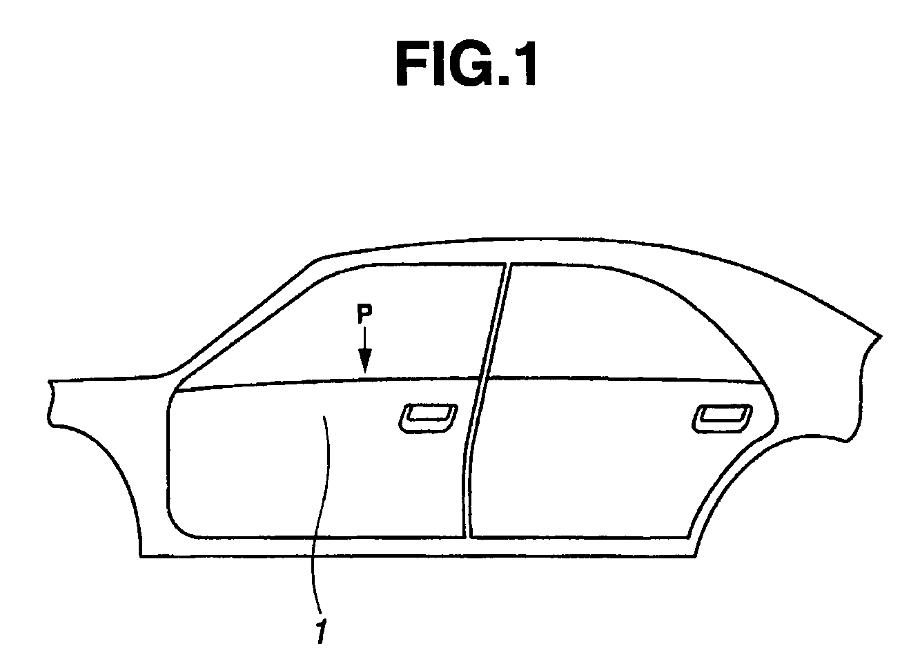
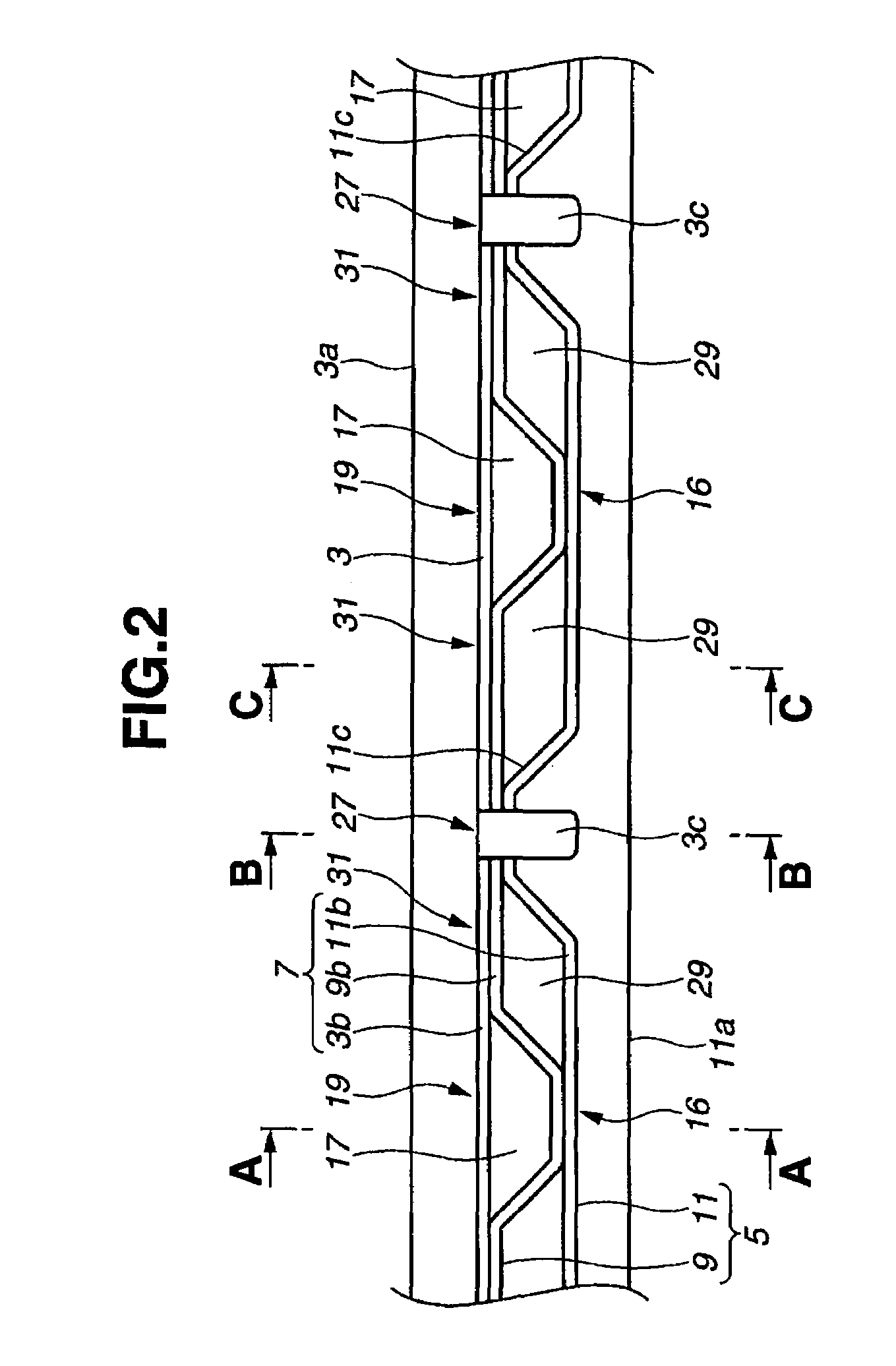
[0027]FIG. 1 is side view of a part of an automobile to which a door panel structure of the invention is applied. FIG. 2 is a plan view of waist flange 7 of the door panel structure at door waist 1 of the automobile as shown in FIG. 1, when viewed from a direction of arrow P shown in FIG. 1. Waist flange 7 includes door panel 3 (i.e. inner panel) and door waist reinforcement 5 at door waist 1.
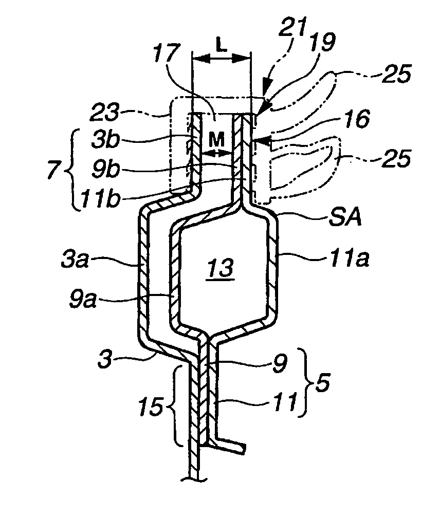
[0028]FIG. 3A is a cross section taken along line A-A of FIG. 2, FIG. 3B is a cross section taken along line B-B of FIG. 2, and FIG. 3C is a cross section taken along line C-C of FIG. 2. An up-and-down direction in FIGS. 3A-3C indicates a vertical direction of the automobile.
[0029]Door waist 1 of the automobile includes door panel 3 having projecting portion 3a as shown in FIGS. 3A-3C. Projecting portion 3a projects toward an inside of the automobile body and extends over a length of the automobile in a fore-and-aft direction of the automobile body (in a direction perpendicular to a paper surfa...
second embodiment
[0062]FIG. 6 is a plan view of the door panel structure of the present invention. FIG. 7 is a cross section similar to FIG. 3B, but showing the cross section taken along line D-D of FIG. 6.
[0063]In the second embodiment, connecting portion 27 of FIG. 1 is modified as indicated at connecting portion 27A. Specifically, in the first embodiment, at waist flange 7 (flanges 3b, 9b and 11b) shown in FIG. 2, door panel 3 is in the form of a flat plate shape without projections and recesses in the fore-and-aft direction of the automobile body (i.e. in the right-and-left direction in FIG. 2). In contrast, in the second embodiment, inner reinforcement 9 and outer reinforcement 11 are in the form of a flat plate shape without projections and recesses in the fore-and-aft direction of the automobile body.
[0064]Further, similar to the first embodiment, flange connecting portion 16A is formed by connecting and fixing flat-plate shaped flanges 9b and 11b of inner and outer reinforcements 9 and 11 to...
PUM
 Abstract
Description
Claims
Application Information
 - R&D
- Intellectual Property
- Life Sciences
- Materials
- Tech Scout
- Unparalleled Data Quality
- Higher Quality Content
- 60% Fewer Hallucinations
Browse by: Latest US Patents, China's latest patents, Technical Efficacy Thesaurus, Application Domain, Technology Topic, Popular Technical Reports.
© 2025 PatSnap. All rights reserved.Legal|Privacy policy|Modern Slavery Act Transparency Statement|Sitemap|About US| Contact US: help@patsnap.com


