Bone screw for fixing osteoporosis bone

A technology for osteoporosis and bone screw, applied in the field of bone screw to achieve the effect of improving health and nutritional status

Active Publication Date: 2013-04-03
SHENZHEN INST OF ADVANCED TECH
View PDF3 Cites 9 Cited by
  • Summary
  • Abstract
  • Description
  • Claims
  • Application Information

AI Technical Summary

Problems solved by technology

However, when it is necessary to deal with complications after bone cement curing or to improve the health and nutritional status of the surrounding osteoporotic bone, the current design of hollow channel bone screws cannot meet the needs of this work

Method used


Image

  • Bone screw for fixing osteoporosis bone
  • Bone screw for fixing osteoporosis bone
  • Bone screw for fixing osteoporosis bone

Examples


Embodiment Construction

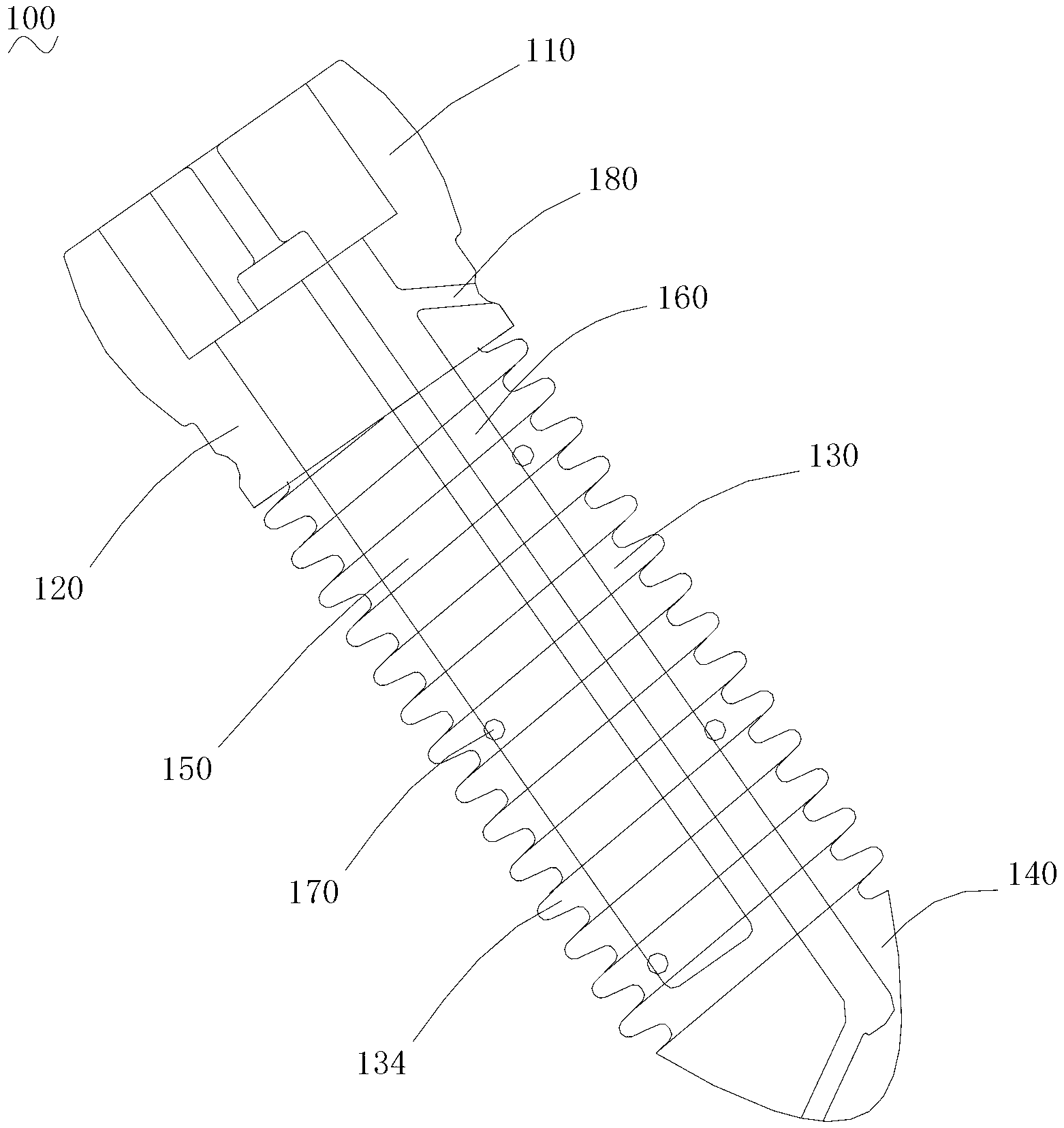
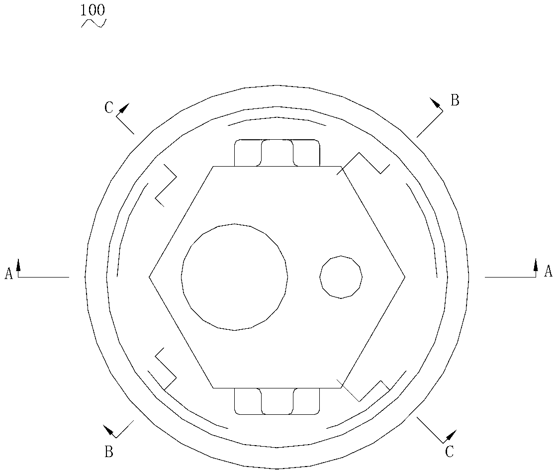
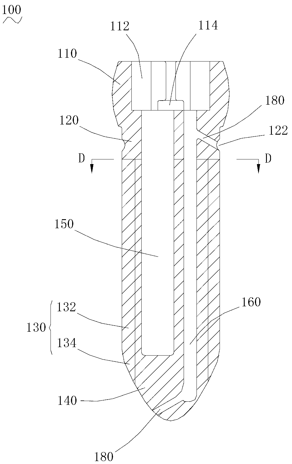
[0023] Please refer to Figure 1 to Figure 6 , a bone screw 100 for fixing osteoporotic bone in one embodiment includes a bone screw body, and the bone screw body includes a head 110 , a neck 120 , a bolt body 130 and a tail 140 connected in sequence.

[0024] Please refer to Figure 1 to Figure 3 , the head 110 is provided with an axial regular hexagonal groove 112, which facilitates subsequent use of tools to remove the bone screw from the bone. The opposite side walls of the regular hexagonal groove 112 are respectively provided with an inverted T-shaped groove structure 114, and the opening of the inverted T-shaped groove structure 114 is located on the upper surface of the head 110, which is also to facilitate the removal of the screw. And design. The bottom of the regular hexagonal groove 112 is respectively provided with a parallel first channel 150 and a second channel 160 along the axial direction, wherein the first channel 150 runs through the neck 120 and extends ...


PUM


Abstract

The invention relates to a bone screw for fixing an osteoporosis bone. The bone screw comprises a bone screw body; the internal part of the bone screw is provided with a first axial channel and a second axial channel; a first radial hole communicated with the first channel and a second radial hole communicated with the second channel are formed in the surface of the bone screw body. According to the bone screw provided by the invention, as the two internal channels are arranged, the bone screw can finish bone cement filling by utilizing one of the channels in the osteoporosis fracture bone, and the other channel can be utilized to perform relevant drug or nutrient substance conveying, so that the complication diseases after the bone cement is solidified can be dealt with and the health and nutrition conditions of surrounding osteoporosis bones can be improved.

Description

technical field [0001] The invention relates to the field of medical devices, in particular to a bone screw for osteoporotic bone fixation. Background technique [0002] Bone screws, such as pedicle screws, dynamic hip screws, etc., are used for hip and spine internal fixation implants. This technique has been used as a common implant technique for the treatment of fractures or bone deformations. Bone screws are usually inserted into the bone for fixation, but for patients diagnosed with osteoporosis, the bonding force between the bone screw and the bone is greatly reduced, and it is necessary to fill the drill on the bone with bone cement before inserting the bone screw. hole. However, the filling amount of bone cement and the filling area of ​​bone cement are difficult to control, and cement leakage often occurs, which is likely to cause complications. Therefore, the design of some hollow channel bone screws has appeared, and the bone screws with this design can strengt...

Claims


Application Information

Patent Timeline
Patent Type & Authority Applications(China)
IPC IPC(8): A61B17/86
Inventor 窦庶华吕维加潘浩波高楠莎
Owner SHENZHEN INST OF ADVANCED TECH
Why Eureka
Try Eureka