
A wear tip holder for a VSI crusher, a kit comprising a wear tip holder, and a method of reducing the wear rate of a wear tip holder

一种磨损速度、保持器的技术,应用在谷物处理等方向,达到增强保持能力、减少磨损、摩擦作用增大的效果

Active Publication Date: 2013-04-03
SANDVIK INTPROP AB
View PDF6 Cites 4 Cited by
  • Summary
  • Abstract
  • Description
  • Claims
  • Application Information

AI Technical Summary

Problems solved by technology

Replacement of worn parts requires considerable downtime of the VSI crusher for overhaul

Method used


Image

  • A wear tip holder for a VSI crusher, a kit comprising a wear tip holder, and a method of reducing the wear rate of a wear tip holder
  • A wear tip holder for a VSI crusher, a kit comprising a wear tip holder, and a method of reducing the wear rate of a wear tip holder
  • A wear tip holder for a VSI crusher, a kit comprising a wear tip holder, and a method of reducing the wear rate of a wear tip holder

Examples


Embodiment Construction

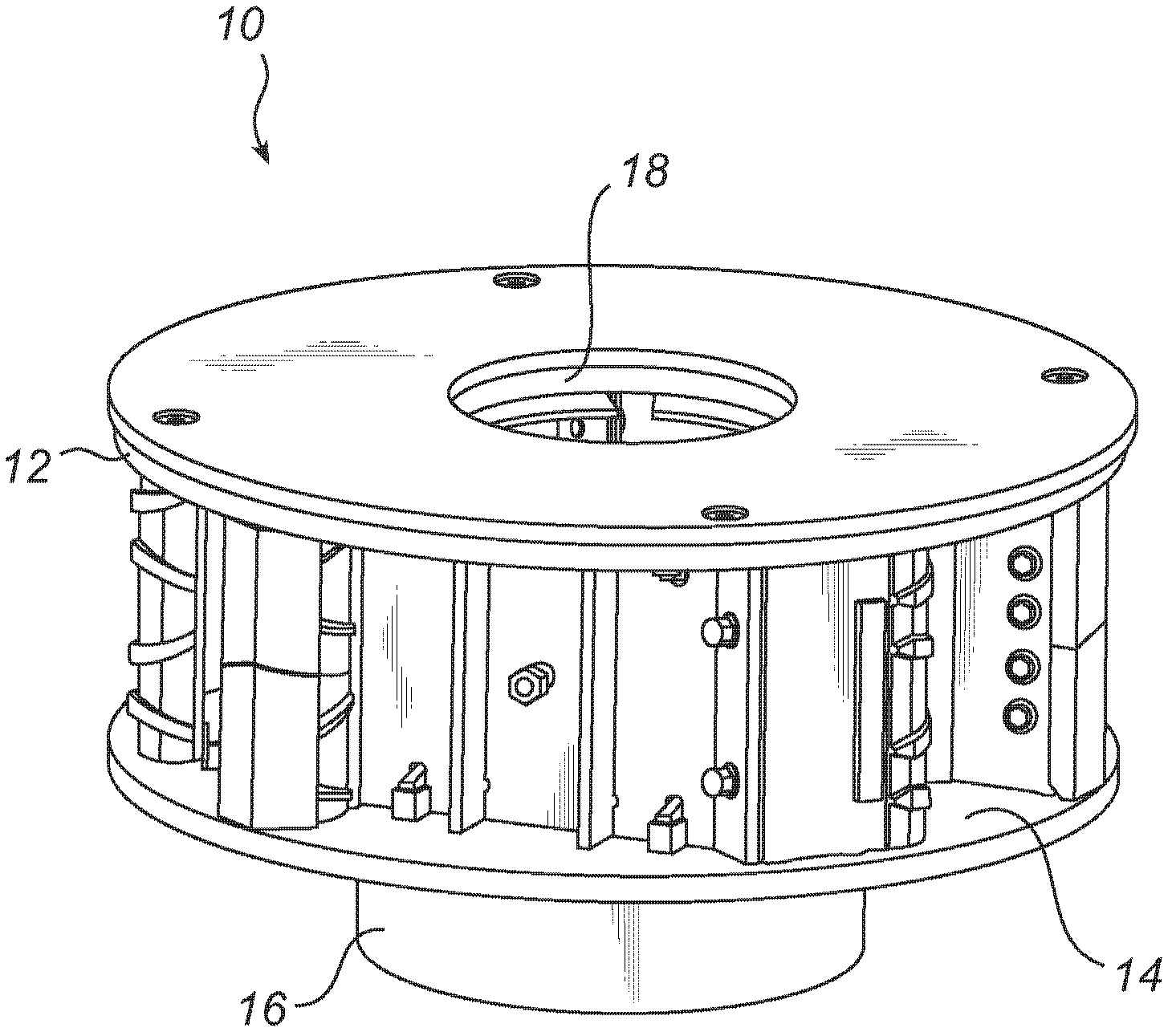
[0037] figure 1Shown is a rotor 10 for use in a vertical shaft impact crusher, ie a VSI crusher. The rotor 10 has a top in the form of a horizontal upper disk 12 and a bottom in the form of a horizontal lower disk 14 . The lower disc 14 has a hub 16 welded to the disc 14 . The hub 16 will be connected to a shaft (not shown) for rotating the rotor 10 within the housing of the VSI crusher. The upper disk 12 has a central hole 18 through which the material to be crushed can be fed into the rotor 10 .

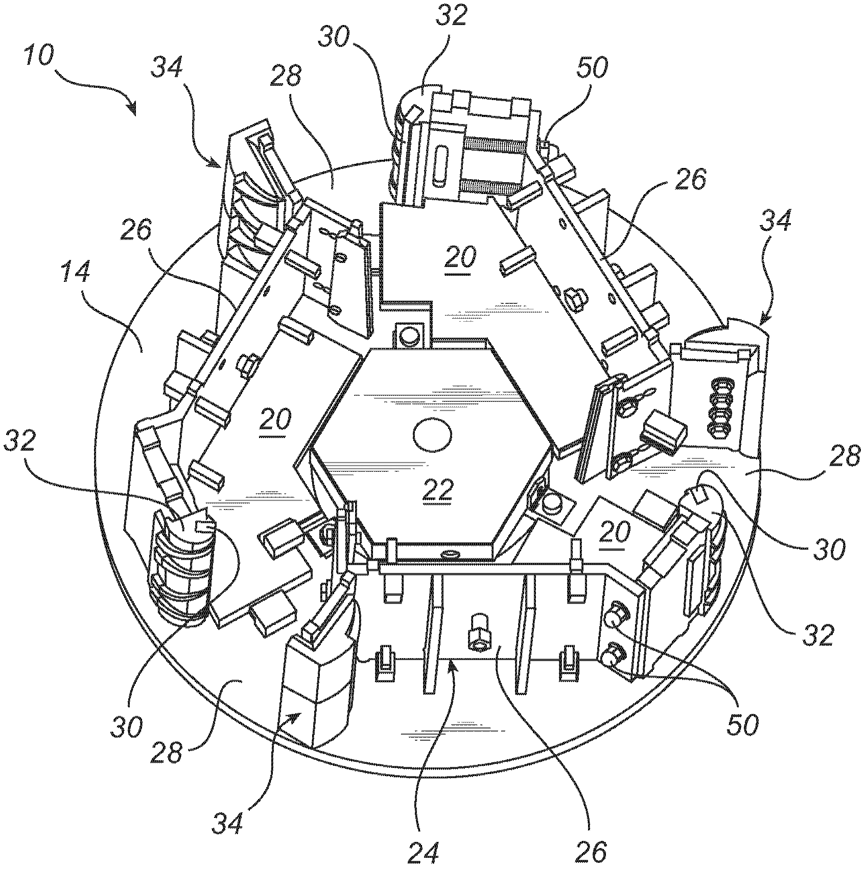
[0038] like figure 2 As shown, the lower disc 14 is protected from wear by a lower wear plate 20 . A distribution plate 22 is fastened to the center of the lower pan 14 . The distribution plate 22 distributes through the holes 18 in the upper plate 12 ( figure 1 ) and supplied materials.

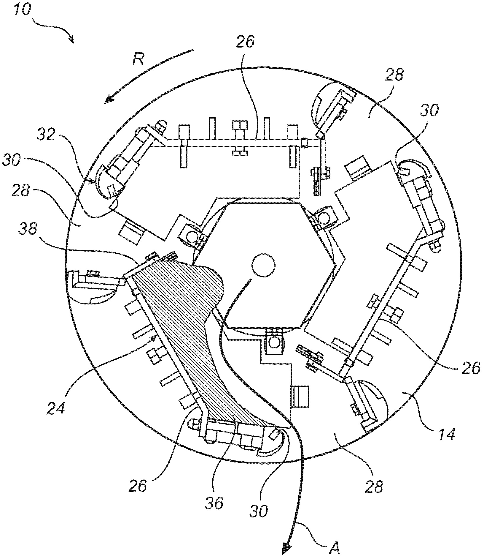
[0039] The upper disk 12 and the lower disk 14 are separated and held together by a vertical rotor wall 24 which is divided into three separate wall sections 26 . The gaps between the wa...


PUM


Abstract

The invention provides a wear tip holder, for holding a wear tip adjacent to an outflow opening of a vertical rotor wall of a rotor of a VSI crusher. The wear tip holder comprises a mounting plate (44) for mounting the wear tip holder (32) to said rotor wall, the mounting plate (44) having a mounting face for facing the rotor wall to which it is to be mounted and a wear face (54) for facing the interior of the rotor. The wear face (54) is provided with at least one material retention hole (58) for retaining, at the wear face (54), at least one of a wear-resistant insert and material to be crushed.

Description

technical field [0001] The invention relates to a wear tip holder for holding a wear tip close to an outflow opening of a vertical rotor wall of a rotor of a VSI crusher. The invention also relates to a kit comprising such a wear tip holder, and a method of reducing the rate of wear of the wear tip holder. Background technique [0002] Vertical shaft impact crushers (VSI crushers) are used in many applications for crushing hard materials such as rocks, ores, etc. A VSI crusher includes a housing and a horizontal rotor inside the housing. WO2008133568 (A1 ) discloses an example of a rotor of a VSI crusher. The material to be crushed is vertically fed into the rotor, and the material is sprayed to the inner wall of the casing by the centrifugal force of the rotating rotor. As the material hits the walls of the housing, the material is broken into the desired size. The housing wall may be provided with anvils or with a bed of residual material upon which the accelerated mat...

Claims


Application Information

Patent Timeline
Patent Type & Authority Applications(China)
IPC IPC(8): B02C13/18B02C13/282
CPCB02C13/1835B02C13/2804B02C13/1842B02C13/28
Inventor 罗恩·达利莫尔克努特·凯兰安德烈亚斯·福斯伯格
Owner SANDVIK INTPROP AB
Learn More