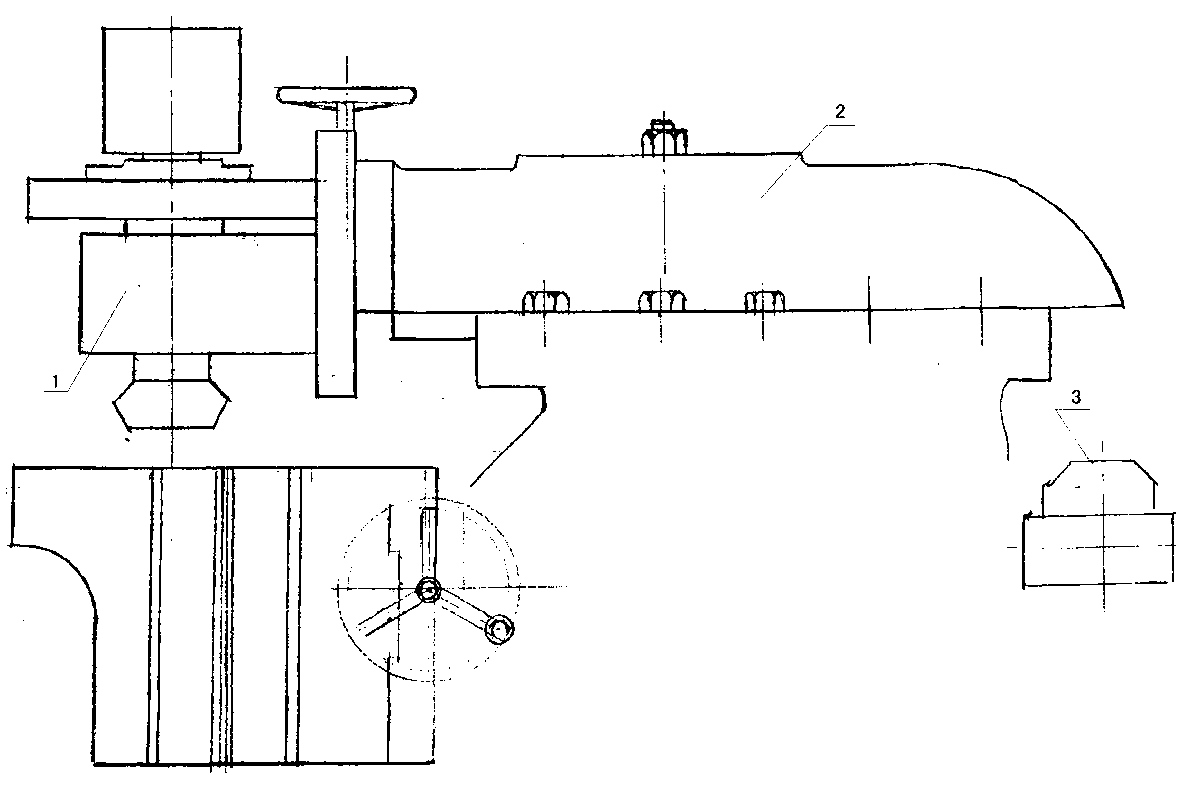
Milling machine
A technology of milling machine and bed, applied in milling machine, milling machine equipment, clamping and other directions, can solve the problem of automatic tool change failure, time-consuming and other problems, to facilitate manual tool change, reduce the number of tool changes, and improve work reliability Effect
Inactive Publication Date: 2013-04-03
DALIAN HENRY CASTING
View PDF0 Cites 4 Cited by
- Summary
- Abstract
- Description
- Claims
- Application Information
AI Technical Summary
Problems solved by technology
The traditional milling machine design has detailed information and mature experience for reference and reference, but the tool change during processing can realize sequential processing of various surfaces, but each tool change takes a lot of time, especially automatic tool change sometimes fails
Method used
View moreImage
Smart ImageViewing Examples
Examples
Embodiment 1
[0012] A milling machine, including a bed, a workbench and slide rails, is characterized in that it also includes a milling head 1 and a cutter 2. The milling machine also includes an automatic tool feeding device 3 . The automatic knife feeding device slides laterally. The milling machine also includes a manual tool feeding device. The manual knife feeding device slides longitudinally.
Login to View More PUM
 Abstract
The invention discloses a milling machine. The milling machine comprises a machine body, a workbench and a sliding rail, and is characterized by further comprising a milling head (1), a cutter (2), an automatic cutter feeding device (3) sliding transversely and a manual cutter feeding device sliding longitudinally. An adjusting technology of the milling machine can reduce the cutter changing times to the maximum extent and facilitates manual change of the cutter; and a machining center can automatically change the cutter, so that on the premise of meeting machining requirements, through reduction of the cutter changing times, the auxiliary time can be saved and the working reliability of the milling machine can be improved.
Description
technical field [0001] The invention relates to the field of machining, in particular to a milling machine. Background technique [0002] Milling machines are commonly used in machining. Milling machines and machining centers have been widely used in recent years. With their high processing efficiency, high precision and high adaptability to workpieces, traditional machining has undergone tremendous changes. The traditional milling machine design has detailed information and mature experience for reference and reference, but the tool change during processing can realize sequential processing of various surfaces, but each tool change takes a lot of time, especially automatic tool change sometimes fails . Contents of the invention [0003] Aiming at the requirement of the prior art on product processing precision control, the present invention provides a milling machine, which includes a bed, a workbench and a slide rail, and is characterized in that it also includes a mil...
Claims
Login to View More Application Information
Patent Timeline
 Patent Type & Authority Applications(China)
IPC IPC(8): B23C1/00B23Q3/155
Inventor 隋成禄
Owner DALIAN HENRY CASTING
Features
- R&D
- Intellectual Property
- Life Sciences
- Materials
- Tech Scout
- Unparalleled Data Quality
- Higher Quality Content
- 60% Fewer Hallucinations
Learn More Browse by: Latest US Patents, China's latest patents, Technical Efficacy Thesaurus, Application Domain, Technology Topic, Popular Technical Reports.
© 2025 PatSnap. All rights reserved.Legal|Privacy policy|Modern Slavery Act Transparency Statement|Sitemap|About US| Contact US: help@patsnap.com

