
An automatic feeding and discharging roller conveyor

A roller conveyor, feeding and discharging technology, applied in the field of conveyors, can solve the problems of inability to achieve effective material transition, mechanical failure at the transition, and damage to the raceway, and achieves a compact and reasonable structure, a smooth and orderly transition process, and a high degree of automation. Effect

Active Publication Date: 2015-12-16
WUXI BAOHE MACHINERY EQUIP
View PDF5 Cites 1 Cited by
  • Summary
  • Abstract
  • Description
  • Claims
  • Application Information

AI Technical Summary

Problems solved by technology

[0003] Generally, the connection of the power raceways at both ends adopts the direct docking method, which is prone to problems such as poor transition and damage to the raceway, especially when the transported object is heavy, it is often easy to cause mechanical failure at the transition
In addition, in actual production, it is often necessary to feed in and out materials. The transportation relationship between them may be conveyor belt to conveyor belt, or material table to conveyor belt. transition

Method used


Image

  • An automatic feeding and discharging roller conveyor
  • An automatic feeding and discharging roller conveyor
  • An automatic feeding and discharging roller conveyor

Examples


Embodiment Construction

[0024] The technical solutions of the present invention will be further described below in conjunction with the accompanying drawings and through specific implementation methods.

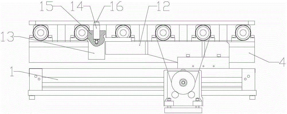
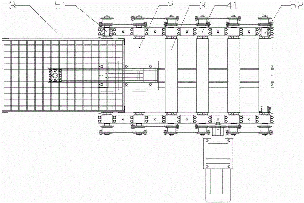
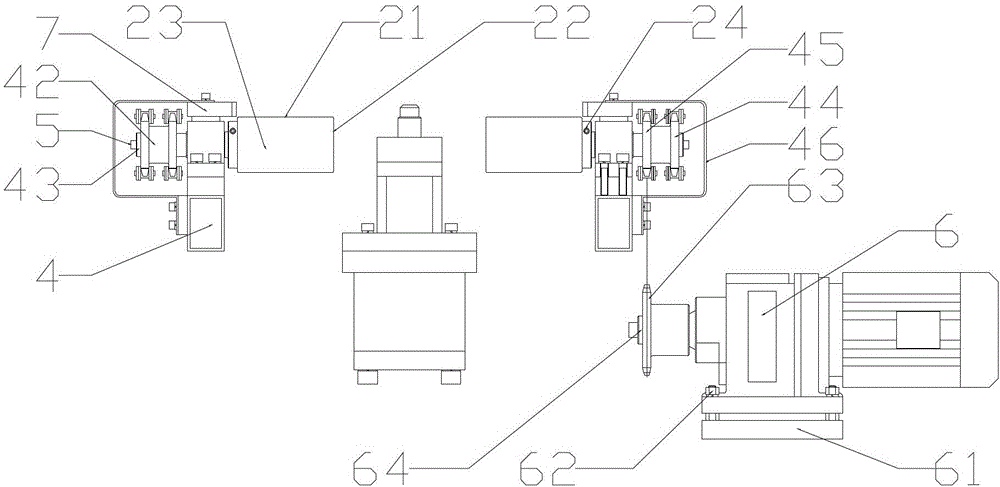
[0025] Figure 1-3 It is a structural schematic diagram of an automatic feeding and discharging roller conveyor provided by a specific embodiment of the present invention.

[0026] An automatic feeding and discharging roller conveyor, including a raceway formed by a driving roller, a power device for driving the driving roller to move, and a frame supporting the driving roller and the power device. The feeding device includes a rodless cylinder 1, a cylinder backing plate 11 located at the bottom of the rodless cylinder 1, a push-pull rod 12 connected with the piston slider on the top of the rodless cylinder 1, and the right part of the push-pull rod 12 is provided with a push-pull pin guide seat 13. The inside of the pin guide seat 13 is provided with a push-pull pin 14, and the drive roller inclu...


PUM


Abstract

The invention discloses an automatic feeding and discharging roller conveyor, which comprises a raceway, a power device and a rack. The automatic feeding and discharging roller conveyor is significantly characterized in that a feeding and discharging device is arranged under one end of the raceway and comprises a rodless cylinder, a cylinder pad plate arranged on the lower part of the rodless cylinder and a push-pull rod connected with a piston sliding block on the upper part of the rodless cylinder, the right part of the push-pull rod is provided with a push-pull pin guide seat, a push-pull pin is arranged in the push-pull pin guide seat, a transmission roller comprises two half rollers and an overall roller, and a gap is arranged between the two corresponding half rollers. The automatic feeding and discharging roller conveyor has the beneficial effects of transition between two power raceways can be realized, transition between a material platform and the conveyor can also be realized, and the problems of non-smooth transition and damage to the raceway can be solved effectively. Moreover, automatic feeding and discharging roller conveyor has the advantages of high degree of automation, smooth and orderly transition, compact and reasonable structure and less occupied space.

Description

technical field [0001] The invention relates to the field of conveyors, in particular to a roller conveyor with automatic feeding and discharging functions. Background technique [0002] Conveyor is a material handling machine that continuously conveys materials on a certain line, also known as continuous conveyor. Multiple roller lines and other conveying equipment or special planes can be used to form a complex logistics conveying system. The roller conveyor adopting the accumulation method can easily realize the accumulation and transportation of materials. In addition, the roller conveyor also has the characteristics of simple structure, high reliability and convenient maintenance. [0003] Generally, the connection of the power raceways at both ends adopts the direct docking method, which is prone to problems such as poor transition and damage to the raceway, especially when the transported object is heavy, it is often easy to cause mechanical failure at the transition....

Claims


Application Information

Patent Timeline
Patent Type & Authority Patents(China)
IPC IPC(8): B65G47/52B65G13/07B65G47/82
Inventor 邱红伟
Owner WUXI BAOHE MACHINERY EQUIP
Learn More