Yarn winding machine and yarn winding unit

A technology of a winding machine and yarn, applied in the structural field of the yarn splicing part, can solve the problems of inability to guarantee, insufficient inspection accuracy of the yarn splicing part, etc.

Active Publication Date: 2013-04-03
MURATA MASCH LTD
View PDF8 Cites 11 Cited by
  • Summary
  • Abstract
  • Description
  • Claims
  • Application Information

AI Technical Summary

Problems solved by technology

However, the above-mentioned empirical formula cannot be guaranteed to be applicable to all conditions, and it is difficult to say that an accurate yarn moving speed can always be obtained.
Therefore, the inspection accuracy of the yarn splicing portion in the yarn splicing portion monitoring device is not sufficient, and there is room for improvement in consideration of this situation.

Method used


Image

  • Yarn winding machine and yarn winding unit
  • Yarn winding machine and yarn winding unit
  • Yarn winding machine and yarn winding unit

Examples


Embodiment Construction

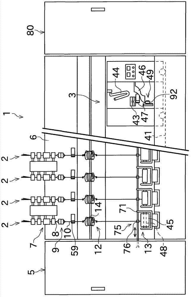
[0037] Next, a spinning machine as a yarn winding machine according to an embodiment of the present invention will be described with reference to the drawings. figure 1 The illustrated spinning machine (spinning machine) 1 has: a plurality of spinning units (yarn winding units) 2 arranged in parallel; a yarn splicing trolley 3; a fan box 80;

[0038] A negative pressure source and the like for supplying negative pressure to each spinning unit 2 are arranged in the fan box 80 . A drive source common to the spinning units 2 is arranged in the prime mover case 5 .

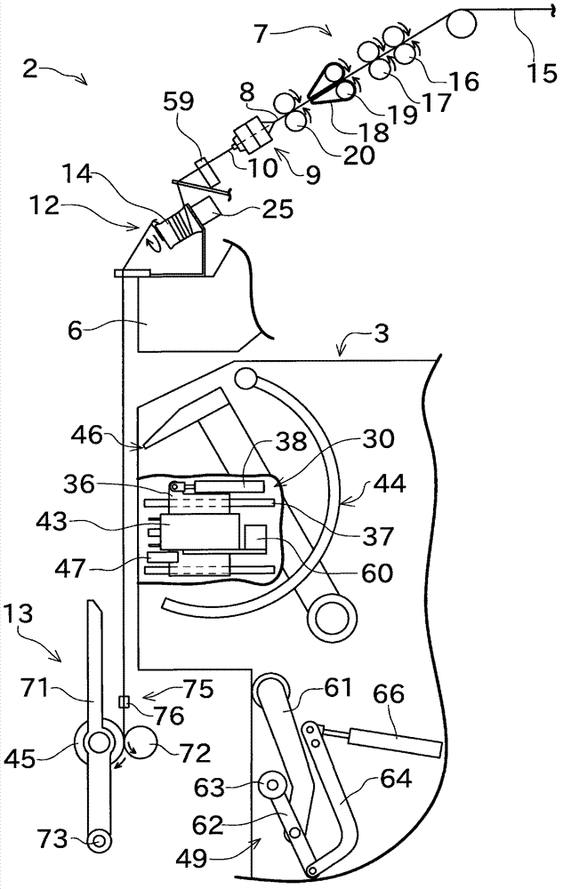
[0039] Such as figure 2 As shown, each spinning unit 2 has a draft device 7, a spinning device (yarn feeding section) 9, a yarn accumulating device 12, and a winding device (winding section) 13 arranged sequentially from upstream to downstream. Each spinning unit 2 spins the fiber bundle 8 sent from the drafting device 7 in the spinning device 9 to generate a spun yarn 10, and the spun yarn 10 is wound on a bobbin ...


PUM


Abstract

The invention provides a yarn winding machine and a yarn winding unit. A spinning frame includes a winding device (13), a spinning device (9), a rotary encoder mechanism (52), a yarn joining device (43), a yarn joint monitor (47), and a carrier controller. The winding device (13) winds a spun yarn (10) to form a package (45). The spinning device (9) supplies the spun yarn (10) to the winding device (13). The rotary encoder mechanism detects a rotational speed of the package (45). The yarn joining device (43) joins the spun yarn (10) between the spinning device (9) and the package (45) to form a yarn joint (99). The yarn joint monitor (47) arranged downstream of the yarn joining device (43) in a running direction of the spun yarn (10) monitors the yarn joint. The carrier controller judges whether the yarn joint formed by the yarn joining device (43) is normal based on the moving speed of the spun yarn (10) obtained by the detection result of the rotary encoder mechanism and the monitoring result output from the yarn-joint monitoring device (47).

Description

technical field [0001] The present invention relates to a structure for inspecting a yarn splicing portion of a yarn formed in a yarn splicing device. Background technique [0002] There is known a yarn winding machine that winds yarn on a bobbin to form a package. As such a yarn winding machine, there is, for example, a spinning machine disclosed in JP 2007-284812 A (Patent Document 1). As described in Patent Document 1, this spinning machine has: a spinning section that twists a fiber bundle to produce a spun yarn; winding department. [0003] The spinning machine of Patent Document 1 has a yarn joining trolley that, when the spun yarn between the spinning unit and the package is in a disconnected state, performs a check of the yarn on the side of the spinning unit and the yarn on the side of the package. The yarns are joined (yarn spliced). The yarn joining trolley has a yarn joining device. The yarn joining device joins the yarn end on the spinning unit side and the...

Claims


Application Information

Patent Timeline
Patent Type & Authority Applications(China)
IPC IPC(8): B65H63/06
CPCB65H63/064B65H54/26B65H2701/31B65H67/085B65H69/061B65H61/005
Inventor 上田健一山田修司
Owner MURATA MASCH LTD
Why Eureka
Try Eureka