Fan hub hanger with rotational locking mechanism and using method thereof

A locking mechanism and fan wheel technology, applied in the direction of load hanging components, transportation and packaging, etc., can solve the problems of safety hazards and high cost, and achieve the effects of avoiding safety hazards, reducing production costs, and saving lifting time

Active Publication Date: 2015-07-15
CRRC WIND POWER(SHANDONG) CO LTD
View PDF7 Cites 0 Cited by
  • Summary
  • Abstract
  • Description
  • Claims
  • Application Information

AI Technical Summary

Problems solved by technology

[0008] This spreader is simple in structure and easy to manufacture, but it has certain potential safety hazards, because when the telescopic rod 3 shrinks to a suitable position, the staff needs to climb up and insert the fixed rod 4, which belongs to high-altitude operations.
Inserting the fixed rod 4 requires the help of tooling equipment, which costs a lot

Method used


Image

  • Fan hub hanger with rotational locking mechanism and using method thereof
  • Fan hub hanger with rotational locking mechanism and using method thereof
  • Fan hub hanger with rotational locking mechanism and using method thereof

Examples


Embodiment Construction

[0040] The present invention will be further described below in conjunction with the accompanying drawings and embodiments.

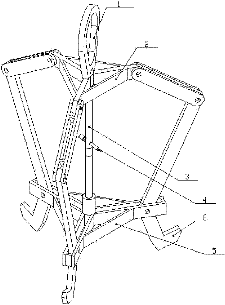
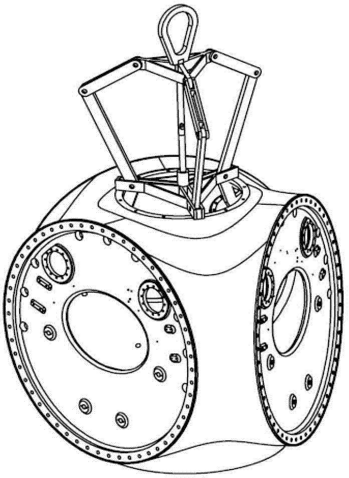
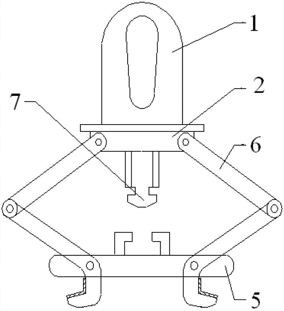
[0041] Such as image 3 As shown, a wind turbine hub hanger with a rotation locking mechanism includes a suspension ring 1, an upper connection module 2, an intermediate connection module 12, a lower connection module 5, a claw module 6 and a rotation locking mechanism 7. The suspension ring 1 Fixed directly above the upper connection module 2, the upper connection module 1 is connected to the middle connection module 12, the middle connection module 12 is connected to the claw module 6, and the claw module 6 is fixed on the lower connection module 5, A rotation locking mechanism 7 is installed directly below the upper connection module 2 , and a slot for matching with the rotation locking mechanism 7 is provided on the upper surface of the lower connection module 5 .

[0042] The claw-shaped module 6 is provided with a plastic protective pad.

[0043...


PUM


Abstract

The invention discloses a fan hub hanger with a rotational locking mechanism and a using method thereof. The fan hub hanger with the rotational locking mechanism comprises a ring, an upper connection module, an intermediate connection module, a lower connection module, a claw module and a rotational locking mechanism, wherein the ring is fixed right above the upper connection module which is connected with the intermediate connection module; the intermediate connection module is connected with the claw module which is fixed on the lower connection module; the rotational locking mechanism is mounted right below the upper connection module; and a slot matched with the rotational locking mechanism is formed on the upper surface of the lower connection module. The invention further discloses a using method for the fan hub hanger with the rotational locking mechanism. The fan hub hanger has the advantage that a worker does not need to ascend to transport a hub.

Description

technical field [0001] The invention relates to a fan wheel hub hanger with a self-rotation locking mechanism and a using method thereof. Background technique [0002] The wheel hub spreader structure of the Chinese patent (application number: 201020660520.2, name: fan hub transport spreader) is as follows figure 1 As shown, it includes a suspension ring 1, an upper connection module 2, a telescopic rod 3, a fixed rod 4, a lower connection module 5, a claw module 6 and an intermediate connection module 12, wherein the suspension ring 1 is fixed above the upper connection module 2, The upper connecting module 2 is triangular, and the protruding parts of each corner of the upper connecting module 2 are connected with respective intermediate connecting modules 12, and each intermediate connecting module 12 is connected with respective claw-shaped modules 6, and the three claws The shape module 6 is fixed on the lower connection module 5, and the upper connection module 2 and t...

Claims


Application Information

Patent Timeline
Patent Type & Authority Patents(China)
IPC IPC(8): B66C1/22
Inventor 于炜东王刚游瑞
Owner CRRC WIND POWER(SHANDONG) CO LTD
Why Eureka
Try Eureka