
A bending node, curved continuous steel truss bridge and its design method

A technology of steel truss bridges and continuous curves, applied in truss bridges, bridges, bridge forms, etc., can solve the problems of inability to adopt steel truss structures and limit the application range of steel trusses, and achieve simple structure, high-efficiency design and Create and create convenient effects

Active Publication Date: 2019-04-16
CHINA MAJOR BRIDGE ENERGINEERING
View PDF6 Cites 0 Cited by
  • Summary
  • Abstract
  • Description
  • Claims
  • Application Information

AI Technical Summary

Problems solved by technology

This structural characteristic of traditional steel truss girders makes it impossible to construct curved steel truss bridges at present by adopting the overall arrangement of straight spans instead of curved ones, that is, the main truss structures of the entire span steel truss girders are still in the same plane, and all The truss joints are still on a straight line, and the arrangement of straight spans instead of curved can only be applied to curved simply supported girder bridges. Therefore, the structural form of steel truss girders cannot be used in the design of curved continuous girder bridges, which severely limits The scope of application of steel truss girders

Method used


Image

  • A bending node, curved continuous steel truss bridge and its design method
  • A bending node, curved continuous steel truss bridge and its design method
  • A bending node, curved continuous steel truss bridge and its design method

Examples


Embodiment Construction

[0032] The present invention will be further described in detail below in conjunction with the accompanying drawings and specific embodiments.

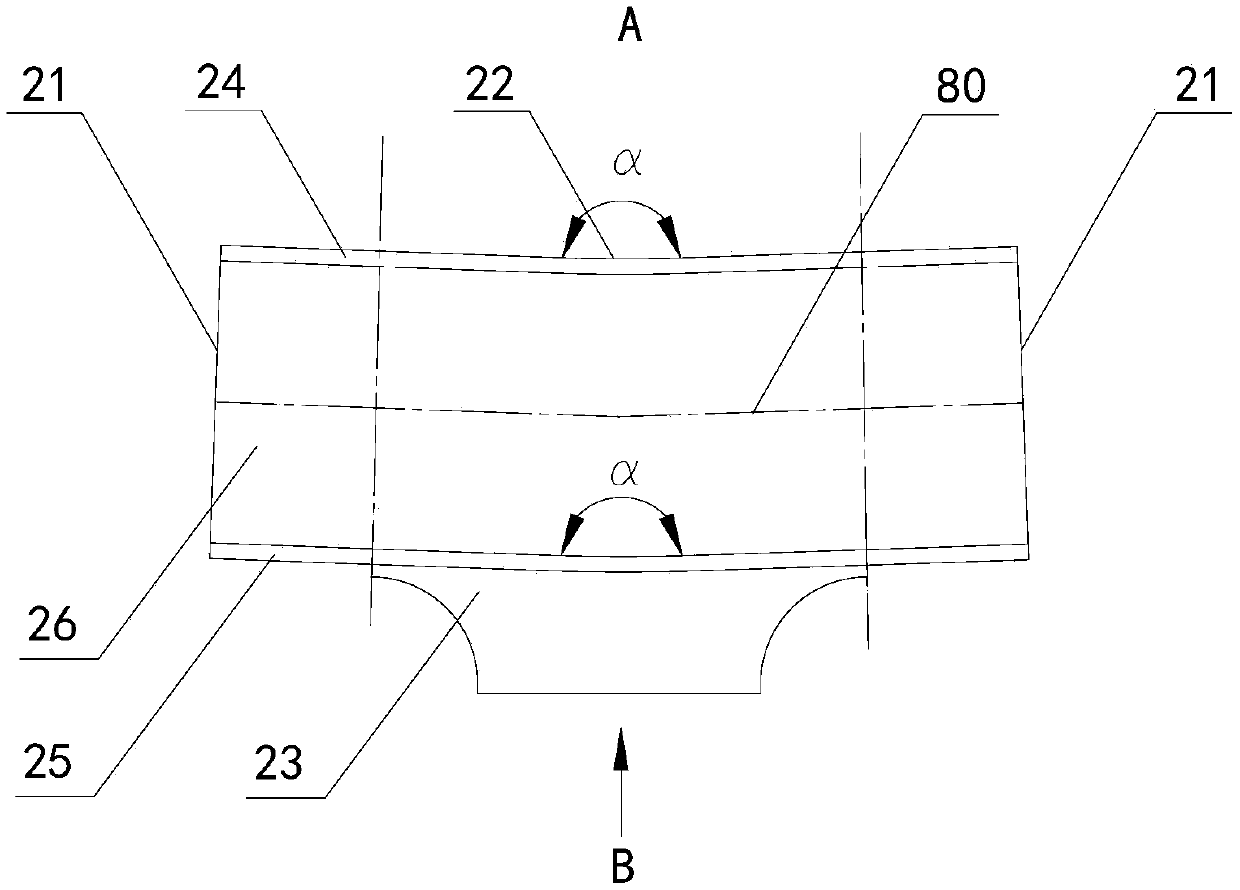
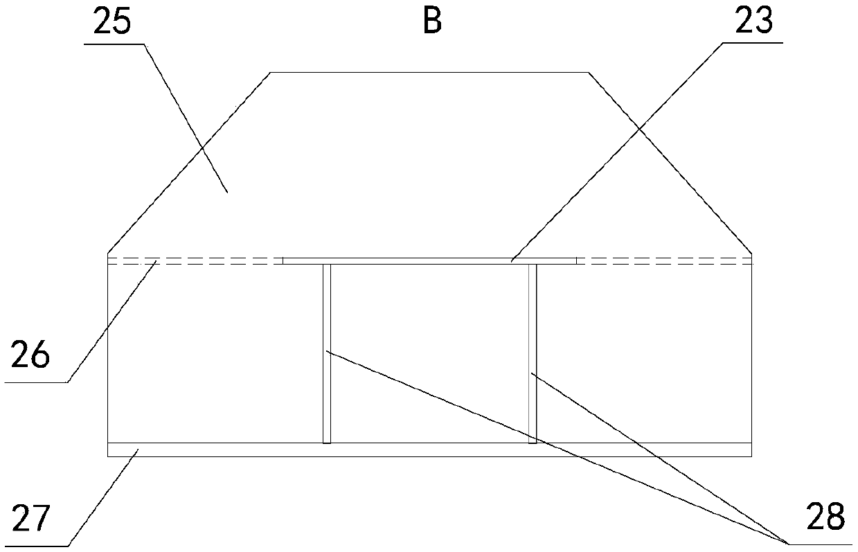
[0033] see figure 1 As shown, the embodiment of the present invention provides a bending node for connecting two adjacent main truss members in a steel truss girder bridge, each main truss member includes an upper chord, a lower chord and a web, and the bending The hinge point 2 is divided into two connecting sections 21 and a bending section 22 arranged between the two connecting sections 21. The end of each connecting section 21 is a free end for connecting the upper chord or the lower chord. The node 2 has a centerline 80 that runs through the two connecting sections 21 and the bent section 22, the centerline of the bent section 22 is an arc, the centerlines of the two connecting sections 21 are straight lines, and are connected through an arc transition, the two A bending angle α is formed between the centerlines of the connectin...


PUM


Abstract

The invention discloses a bent joint, a curved continuous steel truss girder bridge and a design method of the curved continuous steel truss girder bridge, and relates to the technical field of bridges. The bent joint is used for enabling two adjacent main truss rod pieces of the steel truss girder bridge to be connected with each other, and the main truss rod pieces comprise upper chord members,lower chord members and web members. The bent joint is divided into two connecting sections and a bent section arranged between the two connecting sections, the ends of the connecting sections are both free ends to be used for enabling the upper chord members or the lower chord members to be connected, the bent joint is provided with a center line penetrating through the two connecting sections and the bent section, a center line of the bent section is an arc line, center lines of the two connecting sections are both straight lines, a bent angle alpha is formed between the center lines of thetwo connecting sections, and the bent angle alpha is larger than 90 degrees and smaller than 180 degrees; and a transverse linkage plate is further arranged on the side face of the bent section, and the transverse linkage plate is located in the direction where the arc line protrudes or in the opposite direction. According to the bent joint, the curved continuous steel truss girder bridge and thedesign method of the curved continuous steel truss girder bridge, the included angles between every two adjacent main truss rod pieces are changed through bent joints, the center lines of all main truss rod pieces which are connected through the bent joints are approximately continuous curves, and building of the curved continuous steel truss girder bridge is achieved.

Description

technical field [0001] The invention relates to the technical field of bridges, in particular to a bending node, curved continuous steel truss bridge and a design method thereof. Background technique [0002] The steel truss structure is beautiful in shape and has strong spanning ability, and is widely used in building structures and bridge structures. The steel truss bridge consists of two or more pieces of main truss and the transverse connection system connecting the main trusses. Rods, bottom chords and webs. In the traditional steel truss bridge, all the main truss nodes must be arranged in a straight line, and the traditional integral main truss nodes, such as the structural form of welding inside the node and splicing outside the node, must ensure that the connected main truss members The upper chord, lower chord and web are all in the same plane. This structural characteristic of traditional steel truss girders makes it impossible to construct curved steel truss b...

Claims


Application Information

Patent Timeline
Patent Type & Authority Patents(China)
IPC IPC(8): E01D6/00
CPCE01D6/00
Inventor 肖海珠侯健胡文军李华云张建强苑仁安廖贵星吉海燕张金涛周子明
Owner CHINA MAJOR BRIDGE ENERGINEERING
Learn More