I-section steel girder reinforcement small box girder structure

A technology of I-shaped steel girders and small box girders, which is applied in the direction of bridge reinforcement, bridges, bridge maintenance, etc., can solve problems such as difficult construction, increased beam structure weight, impact of bridge piers and foundations, etc., to achieve enhanced lateral stability, The effect of improved lateral force and reasonable and reliable force

Inactive Publication Date: 2013-04-03
CHINA RAILWAY SIYUAN SURVEY & DESIGN GRP
View PDF8 Cites 14 Cited by
  • Summary
  • Abstract
  • Description
  • Claims
  • Application Information

AI Technical Summary

Problems solved by technology

[0004] 2. Change the original simply supported structure to a continuous structure: After changing to a small box girder with a continuous structure, the longitudinal stiffness increases, the longitudinal force performance is improved, and the driving is smoother, but the more critical transverse force problem has not been improved, and The construction is difficult and has a certain impact on the substructure
[0005] 3. Increase the concrete T-beams: the longitudinal and lateral forces and integrity have been greatly improved, but the only problem is that the pier and foundation also need to be dealt with if the self-weight is too large.
[0006] When a small box girder structure is applied to a highway bridge, if the horizontal spacing of the small box girder girders is too large to a certain extent, the integrity of the bridge structure will be easily weakened, and it may not be effective due to the concentrated force under the vehicle load. The damage caused by the dispersion of the bridge, the bridge disease will gradually spread due to the effect of each break, and the current structure of this type of disease has the problem that the distance between the small box girders is too large to a certain extent
Therefore, strengthening the horizontal connection and improving the integrity of the bridge is the key to eradicating this type of disease. However, in the existing reinforcement technology for the above-mentioned small box girder reinforcement: the first two items in the reinforcement measures cannot improve the integrity of the existing bridge structure. However, the third reinforcement measure will have too much impact on the pier and foundation due to the excessive increase in the weight of the beam structure.

Method used


Image

  • I-section steel girder reinforcement small box girder structure
  • I-section steel girder reinforcement small box girder structure

Examples


Embodiment Construction

[0025] The present invention will be further described in detail below in conjunction with the accompanying drawings and specific embodiments.

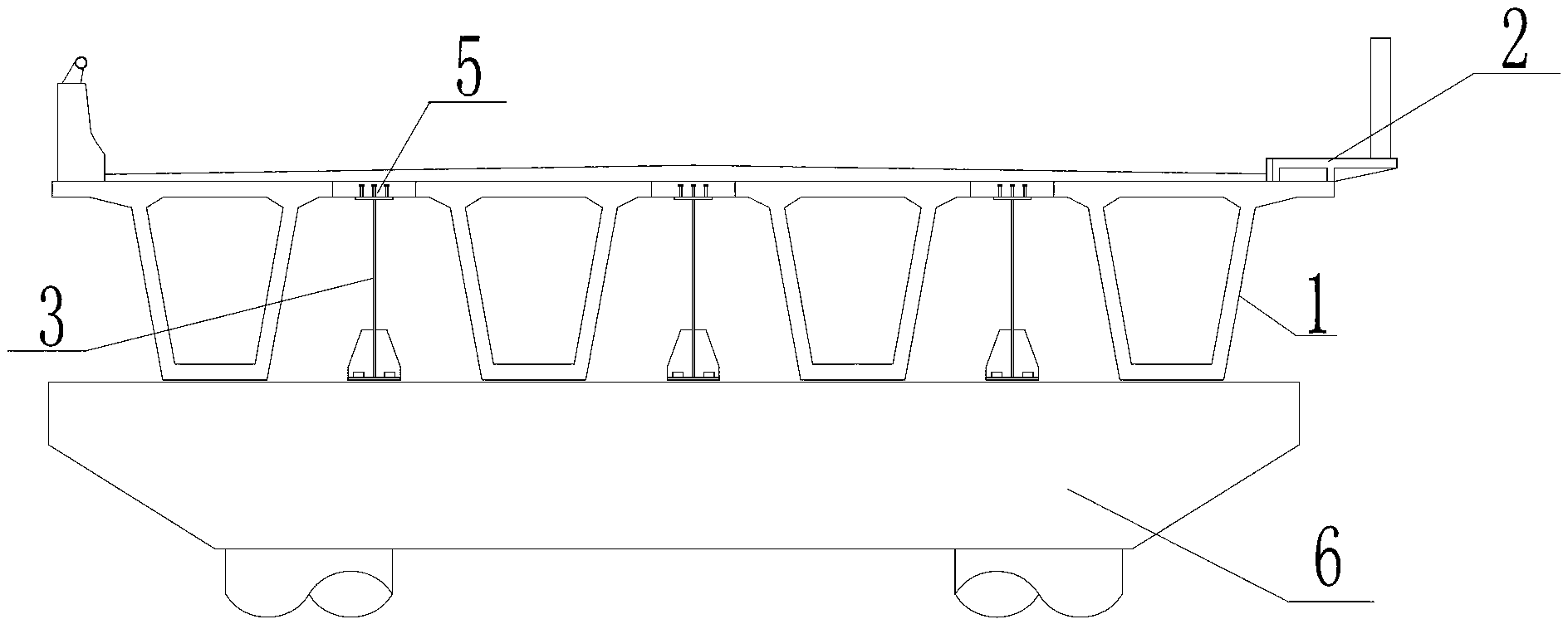
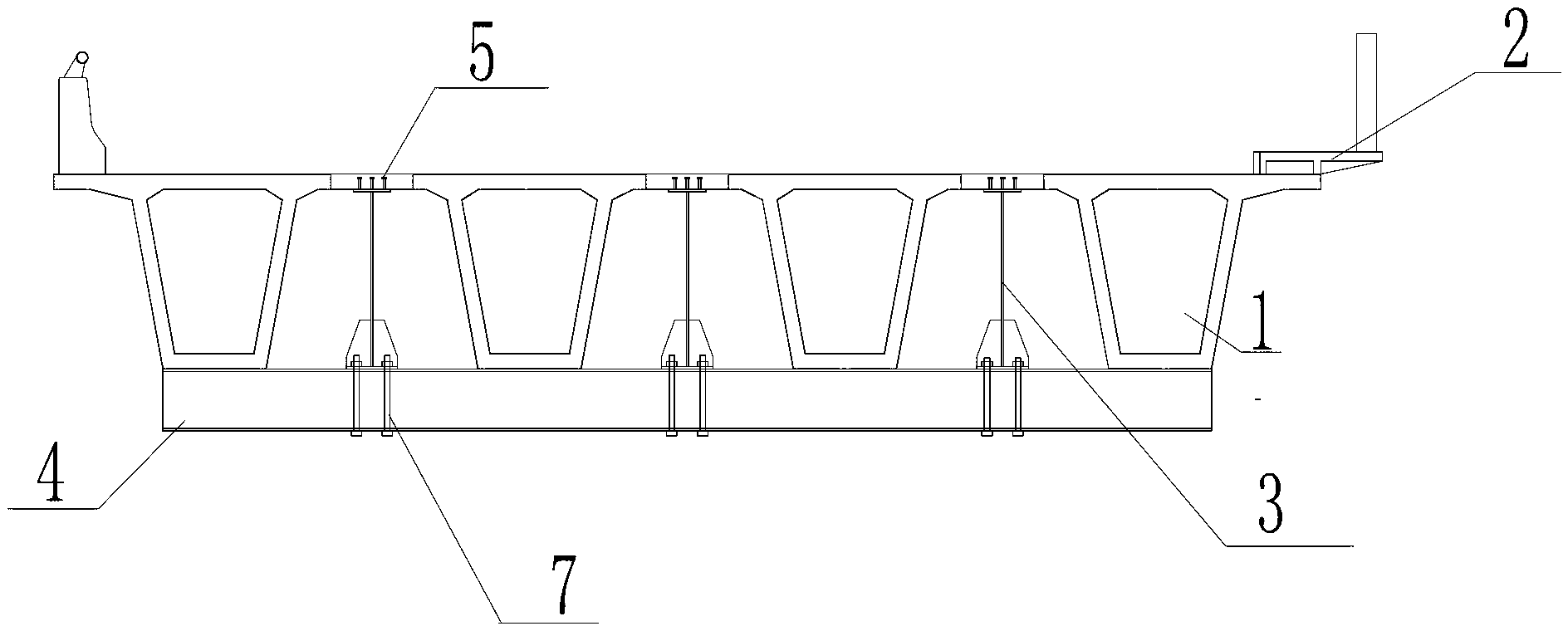
[0026] As shown in the figure, the present invention provides a small box girder structure reinforced with I-shaped steel girders, including a pavement layer 2 and a small box girder 1 arranged side by side on the pier, and the two adjacent small box girders are arranged between There is an I-shaped steel girder 3, the lower end of which is fixed on the pier 6, and the upper end of the I-shaped steel girder 3 is connected and fixed on the flange plate between two adjacent small box girders 1. Flange panels are cast from concrete.

[0027] The shear stud 5 at the upper end of the I-beam 3 is connected and fixed to the flange plate of the small box girder 1 .

[0028] construction process:

[0029] During the construction process, the lower end of the I-shaped steel beam 3 is fixed with the temporary steel beam 4 with bolts 7, so that...


PUM


Abstract

The invention discloses an I-section steel girder reinforcement small box girder structure. The structure comprises a road surface layer and small box girders arranged side by side on a pier, wherein an I-section steel girder is arranged between every two small box girders; the lower ends of the I-section steel girders are fixed at the lower end of the pier; and the upper ends of the I-section steel girders are fixed on flange plates fixed between every two adjacent small box girders. In the invention, the I-section steel girder reinforcement small box girder structure is adopted for the first time, and the new structure is added to bear forces; for inherent weaknesses that the horizontal force is weaker, the integrity is strengthened, so that the force condition becomes better, longitudinal stiffness is enlarged, and the horizontal force is improved; and the structure has the outstanding advantages of reliable technology, and small implementation risk.

Description

technical field [0001] The invention relates to a box girder structure, in particular to a small box girder structure reinforced with I-shaped steel beams. Background technique [0002] At present, the main measures adopted for the small box girder structure of highway bridges that need to be reinforced mainly include: [0003] 1. Add prestress to the original structure: maintain the stress state of the original structure, the longitudinal stiffness remains unchanged, and the lateral force has not been improved. It is to tap its own potential, so the actual burden of the original structure is increased. [0004] 2. Change the original simply supported structure to a continuous structure: After changing to a small box girder with a continuous structure, the longitudinal stiffness increases, the longitudinal force performance is improved, and the driving is smoother, but the more critical transverse force problem has not been improved, and The construction is difficult and ha...

Claims


Application Information

Patent Timeline
Patent Type & Authority Applications(China)
IPC IPC(8): E01D22/00E01D2/04
Inventor 饶少臣严爱国江荣丰曾敏
Owner CHINA RAILWAY SIYUAN SURVEY & DESIGN GRP
Why Eureka
Try Eureka