An assembled sports floor
A floor and sports technology, applied in elastic floors, floors, covering/lining, etc., can solve the problems of stretching expansion joints, time-consuming and laborious installation, easy damage to support bars or the main structure of the floor, etc., and achieve accurate and convenient installation and positioning. Effect
- Summary
- Abstract
- Description
- Claims
- Application Information
AI Technical Summary
Problems solved by technology
Method used
Image
Examples
Embodiment 1
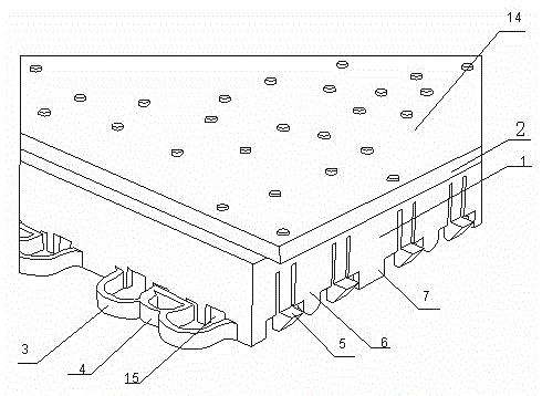
[0027] Such as figure 1 As shown in the structural diagram of the embodiment of the sports floor, the rigid structure layer 1 is a rectangular structure, the two adjacent sides of the side of the rectangular rigid structure layer 1 are the slot ends, and the other two adjacent sides of the side are the buckle ends, which is convenient Multiple rectangular sports floors of the same specification are spliced together to form a whole sports field.
[0028] Wherein the clamping groove ends of the two adjacent sides are several m-shaped elastic clamping grooves 3 extending outwards and distributed at intervals, and the m-shaped elastic clamping grooves 3 are only vertically fixed to the sides of the rectangular rigid structure layer by the bottoms of the left and right sides connection, and the middle of the m-shaped elastic slot 3 is a snap ring 4, and the corresponding snap end has a snap-in protrusion 6 that matches the snap-in ring 4. After the two sports floors are spliced, ...
Embodiment 2
[0032] In the structure of this embodiment, the rigid structure layer 1 is a rectangular structure, and one set of corresponding sides of the side of the rectangular rigid structure layer 1 are the matching slot end and buckle end respectively, and the other set of corresponding sides are curved. The through groove 16 runs through the entire side of the rigid structure layer 1 .
[0033] Such as Figure 5 As shown, when two sports floors with through grooves 16 on the corresponding sides are spliced, the ends of the through grooves 16 of the two rigid structural layers 1 are butted with each other, and after the butt joint, the two rigid structural layers are connected by a U-shaped bar 17, and the U-shaped bar 16 The curved radian of one side matches the radian of the through groove 16, so the through space formed after the two through grooves 16 are docked is consistent with the U-shaped structure of the U-shaped strip 17. The U-shaped strip is an elastic strip. Bar 16 conn...
Embodiment 3
[0039] Such as Image 6As shown in the schematic diagram of the support system structure, the bottom of the rigid structure layer 1 is a rigid support system 8 arranged horizontally and vertically in a staggered manner. Each intersection point of the support system 8 constitutes each leg 9 of the rigid structure layer. The elastic feet 10 together constitute the elastic supporting layer 2 .
[0040] The diagonal positions of each "#"-shaped support unit formed by the horizontal and vertical staggered arrangement of the support system 8 are fixed with hard materials, and each support unit is reinforced, so that the strength of the entire support system 8 is further strengthened. The rigid support system 8 and the rigid material of the rigid structure layer are all made of the same material as the support column in the elastic sports floor of the prior application.
[0041] In the support system 8, there are foot support seats 11 with a hollow structure at the support feet 9 sp...
PUM
 Abstract
Description
Claims
Application Information
 - R&D
- Intellectual Property
- Life Sciences
- Materials
- Tech Scout
- Unparalleled Data Quality
- Higher Quality Content
- 60% Fewer Hallucinations
Browse by: Latest US Patents, China's latest patents, Technical Efficacy Thesaurus, Application Domain, Technology Topic, Popular Technical Reports.
© 2025 PatSnap. All rights reserved.Legal|Privacy policy|Modern Slavery Act Transparency Statement|Sitemap|About US| Contact US: help@patsnap.com


