
Integrated suspended ceiling radiant panel

A radiant panel and integrated technology, applied in the field of radiant panels, can solve problems such as difficult positioning and fixing, complex overall structure, and poor processing efficiency, and achieve the effects of overall volume and weight reduction, good product quality, and convenient laying

Pending Publication Date: 2021-08-10
帝勒森住宅科技(江苏)有限公司
View PDF0 Cites 0 Cited by
  • Summary
  • Abstract
  • Description
  • Claims
  • Application Information

AI Technical Summary

Problems solved by technology

However, the existing radiant panels generally adopt a split assembly structure. During processing, multiple sets of molds need to be used for processing separately, and then combined with corresponding tooling. The processing efficiency is poor, and a large amount of assembly time is required. It is not a plate structure, and it is not easy to locate and fix when it is installed with other plates, resulting in a complex overall structure and a large volume

Method used


Image

  • Integrated suspended ceiling radiant panel
  • Integrated suspended ceiling radiant panel
  • Integrated suspended ceiling radiant panel

Examples


Embodiment Construction

[0027] The preferred embodiments of the present invention will be described in detail below in conjunction with the accompanying drawings, so that the advantages and features of the present invention can be more easily understood by those skilled in the art, so as to define the protection scope of the present invention more clearly. The directional terms mentioned in the present invention, such as "up", "down", "front", "back", "left", "right", "top", "bottom", etc., are only for reference to the attached drawings. direction. Therefore, the directional terms used are used to illustrate and understand the present invention, but not to limit the present invention.

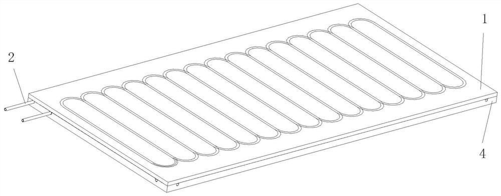
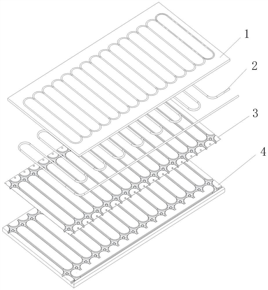
[0028] Such as figure 1 , figure 2 The one-piece ceiling radiant panel shown includes a fireproof base plate 4 , an aluminum plate 3 , a gypsum board 1 and a radiant tube 2 .

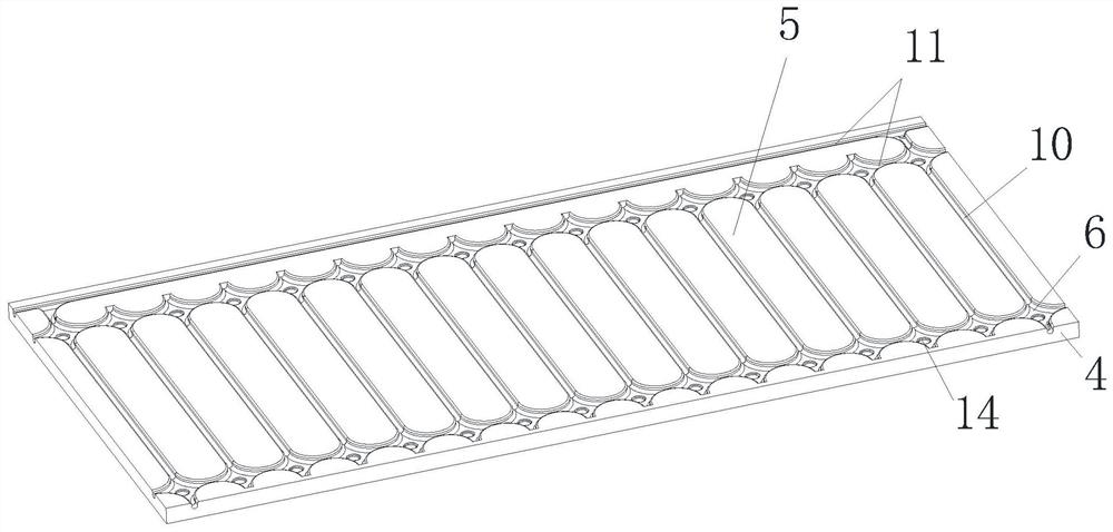
[0029] combine figure 2 , image 3 The shown fireproof substrate 4, the fireproof substrate 4 is a fireproof foam board with a certain...


PUM


Abstract

The invention relates to an integrated suspended ceiling radiant panel. The integrated suspended ceiling radiant panel comprises a fireproof base plate, an aluminum plate, a gypsum plate and radiant pipes, wherein a plurality of parallel first longitudinal grooves and first transverse grooves are evenly distributed in the top face of the fireproof base plate, the aluminum plate covers the top face of the fireproof base plate and is embedded into the first longitudinal grooves and the first transverse grooves, the radiant pipes are embedded into second longitudinal grooves and second transverse grooves, and the gypsum plate covers the top face of the aluminum plate. According to the integrated suspended ceiling radiant panel, an integrally-formed structure is adopted, the trouble of splicing is avoided, the machining efficiency is high, the product quality is good, stacking is convenient, and the manufacturing cost is low; the fireproof base plate, the aluminum plate and the radiant pipes are of an embedded structure, installation and positioning are accurate and convenient, and the overall size and weight are greatly reduced; due to special groove structures of the fireproof base plate and the aluminum plate, various pipe coiling modes can be adopted in the radiant pipes, so that the radiant pipes can be used as pipe openings from all directions, and convenience is provided for laying of the integrated suspended ceiling radiant panel.

Description

technical field [0001] The invention relates to the technical field of radiant panels, in particular to an integrated ceiling radiant panel. Background technique [0002] Radiant panels have gradually become popular because of their energy-saving and comfortable features, and do not occupy the usable area of ​​the room. However, the existing radiant panels generally adopt a split-type assembly structure. During processing, multiple sets of molds need to be used for processing separately, and then combined with corresponding tooling. The processing efficiency is poor, and a large amount of assembly time is required. It is not a plate structure, and it is not easy to locate and fix when it is installed with other plates, resulting in a complex overall structure and a large volume. Contents of the invention [0003] The object of the present invention is to provide an integrated ceiling radiant panel with simple structure, convenient installation, easy processing and molding...

Claims


Application Information

Patent Timeline
Patent Type & Authority Applications(China)
IPC IPC(8): E04F13/08F24F5/00F24D3/14F24D19/00
CPCE04F13/0869E04F13/0875E04F2290/02E04F2290/023E04F2290/047F24D3/141F24D19/0002F24F5/0046
Inventor 李平
Owner 帝勒森住宅科技(江苏)有限公司
Learn More