
Method and apparatus for controlling oil flow in an internal combustion engine

A technology for internal combustion engines and engines, which is applied in the direction of engine lubrication, engine components, machines/engines, etc. It can solve problems such as increasing the friction of cylinder liners and piston rings, affecting fuel consumption and starting performance, and increasing exhaust emissions.

Active Publication Date: 2013-04-03
GM GLOBAL TECH OPERATIONS LLC
View PDF12 Cites 4 Cited by
  • Summary
  • Abstract
  • Description
  • Claims
  • Application Information

AI Technical Summary

Problems solved by technology

Applying excess oil to engine pistons and cylinder walls may result in increased exhaust emissions due to combustion of the excess oil
Applying excess oil to engine pistons and cylinder walls may result in increased friction between the cylinder liner and piston rings, affecting fuel consumption and starting performance

Method used


Image

  • Method and apparatus for controlling oil flow in an internal combustion engine
  • Method and apparatus for controlling oil flow in an internal combustion engine

Examples


Embodiment Construction

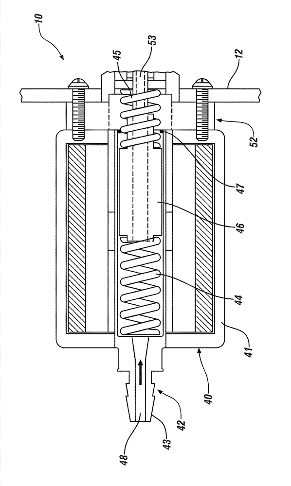
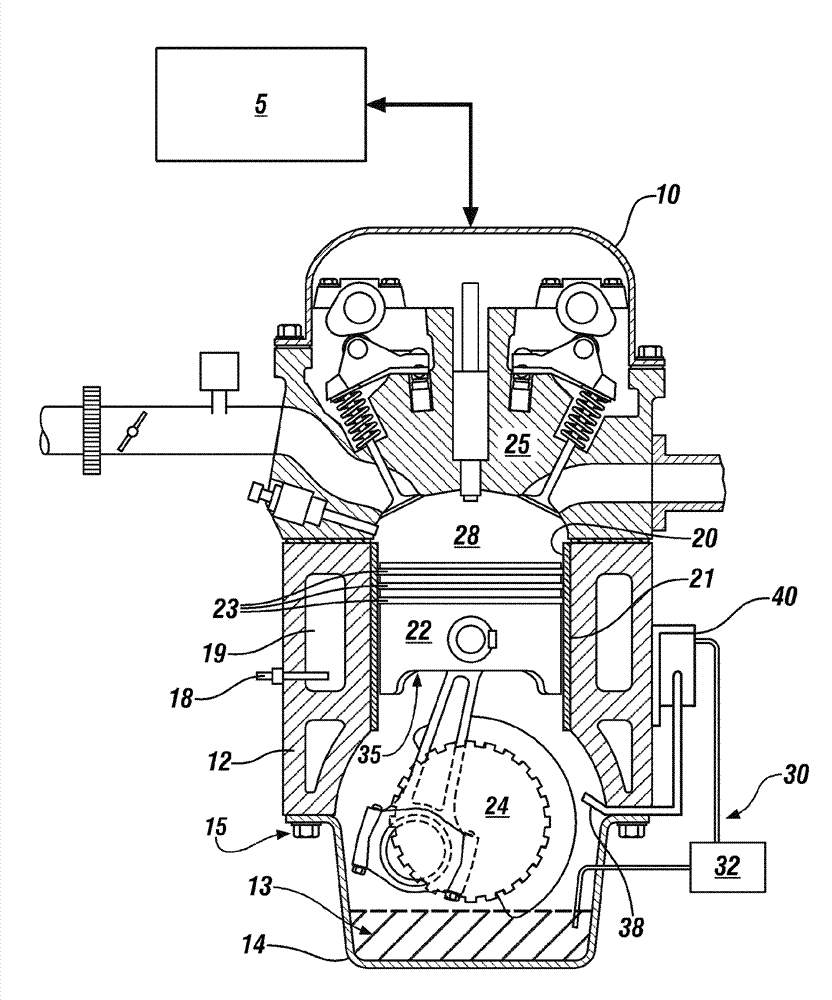
[0034] Referring now to the accompanying drawings, in which the illustrated content is merely to represent some exemplary embodiments and not to limit, figure 1 is a schematic illustration of an internal combustion engine 10 according to the present disclosure. Exemplary engine 10 may be any suitable multi-cylinder internal combustion engine. Engine 10 includes an engine block 12 and a cylinder head 25 . The engine block 12 includes a plurality of cylinders 20 formed therein and a plurality of internally porous coolant passages 19 . The wall portion 21 of each cylinder 20 may comprise a cylinder liner. Each cylinder 20 houses a reciprocating piston 22 connected to a crankshaft 24 . Crankshaft 24 is mechanically coupled to the motor vehicle transmission and driveline to deliver tractive torque thereto in response to an operator torque request. Crankshaft 24 is rotatably connected to lower portion 15 of engine block 12 with main bearings. The oil pan 14 is connected to the ...


PUM


Abstract

The invention relates a method and an apparatus for controlling oil flow in an internal combustion engine. A lubrication system for an internal combustion engine includes an oil jet configured to communicate oil onto an internal engine surface. The oil jet is fluidly connected to a pressurized oil source via an oil flow controller that is configured to control oil flowrate to the oil jet in response to a temperature of the internal engine surface.

Description

technical field [0001] The present disclosure relates to oil flow within an internal combustion engine. Background technique [0002] The statements in this section merely provide background information to which the disclosure is related. Accordingly, these statements do not constitute admissions of prior art. [0003] Lubrication systems for internal combustion engines may use piston nozzles arranged to direct the flow of pressurized engine oil to the underside of the piston to dissipate heat from the piston and provide lubrication of the cylinder walls. A system for providing a flow of pressurized oil to piston nozzles includes an oil pump having an oil flow rate that is controlled in response to engine speed and load. Such systems may include valves configured to inhibit or minimize oil flow to the piston nozzles under low speed / low load conditions. Applying excess oil to engine pistons and cylinder walls may result in increased exhaust emissions due to combustion of t...

Claims


Application Information

Patent Timeline
IPC IPC(8): F01M1/16
CPCF01M1/16F01M1/08
Inventor G.莫杜霍维奇
Owner GM GLOBAL TECH OPERATIONS LLC
Learn More