Centrifugal fan impeller, centrifugal fan and snow blowing vehicle

A centrifugal fan and impeller technology, which is applied in the direction of machines/engines, mechanical equipment, liquid fuel engines, etc., can solve the problems of difficulty adapting to the gas flow characteristics inside the fan, increase the friction between the air flow and the blades, and the low aerodynamic efficiency of the fan, etc., and achieve the overall goal of the fan. Improve efficiency, reduce drag coefficient, and prevent eddy currents

Active Publication Date: 2013-04-03
ZOOMLION ENVIRONMENTAL IND CO LTD
View PDF6 Cites 9 Cited by
  • Summary
  • Abstract
  • Description
  • Claims
  • Application Information

AI Technical Summary

Problems solved by technology

[0004] like figure 1 As shown, a kind of existing centrifugal fan impeller comprises upper blisk 11, lower blisk 12 and many blades 13 that are connected between upper blisk 11 and lower blisk 12, and this blade 13 adopts linear blade, this This type of blade structure is difficult to adapt to the flow characteristics of the gas inside the fan, and it is easy to form a rigid impact of the airflow on the blade, resulting in a serious loss of airflow pressure, so that the airflow inside the impeller of the fan will form a large vortex in the flow channel when the fan is working. This kind of vortex is more intense. The existence of this kind of vortex increases the friction between the airflow and the blades, which cannot meet the requirement of maintaining a relatively stable total pressure when the working conditions of the snow blower fluctuate. energy consumption

Method used


Image

  • Centrifugal fan impeller, centrifugal fan and snow blowing vehicle
  • Centrifugal fan impeller, centrifugal fan and snow blowing vehicle
  • Centrifugal fan impeller, centrifugal fan and snow blowing vehicle

Examples


Embodiment Construction

[0030] In order to make the object, technical solution and advantages of the present invention clearer, the implementation manner of the present invention will be further described in detail below in conjunction with the accompanying drawings.

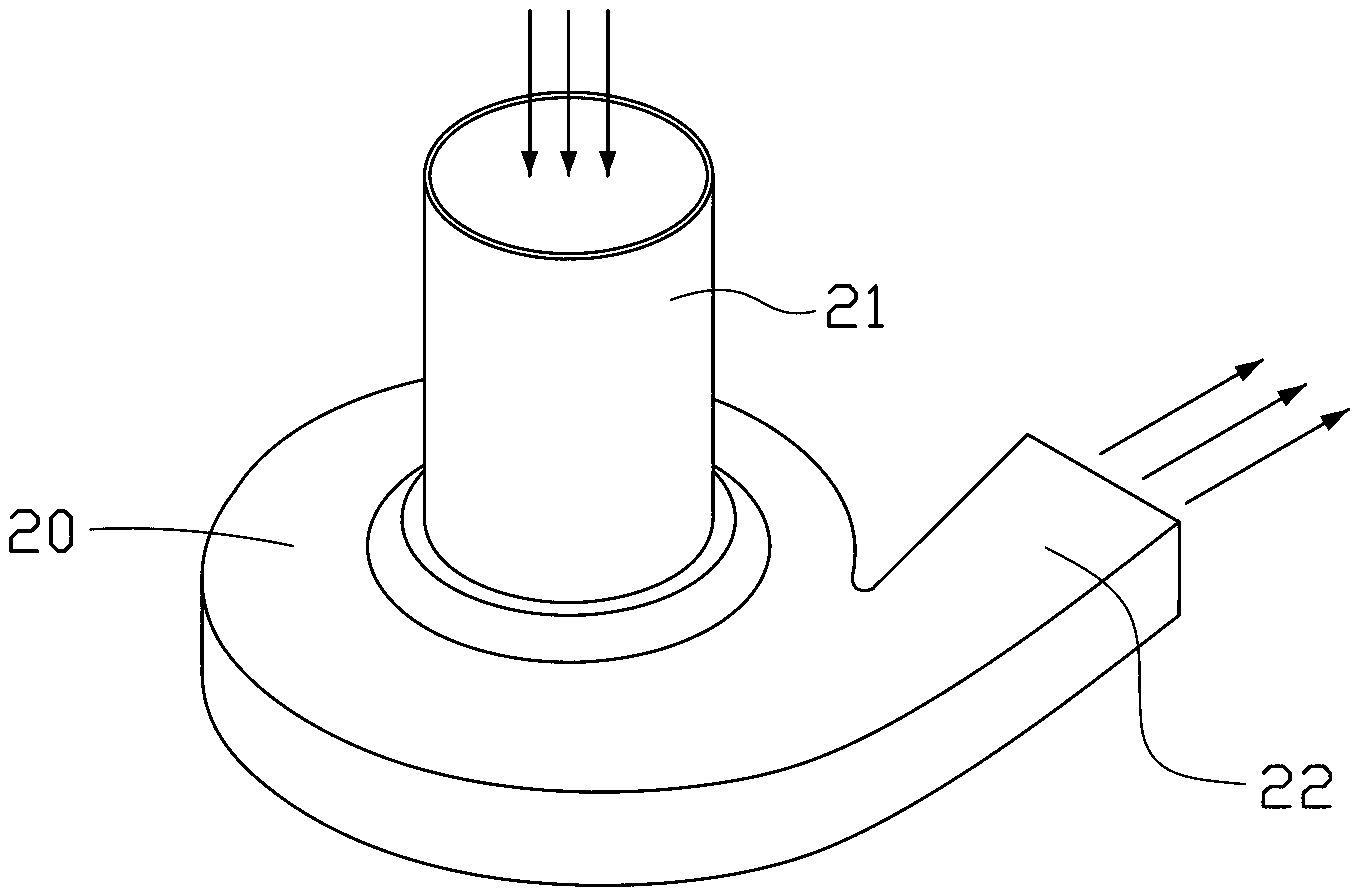
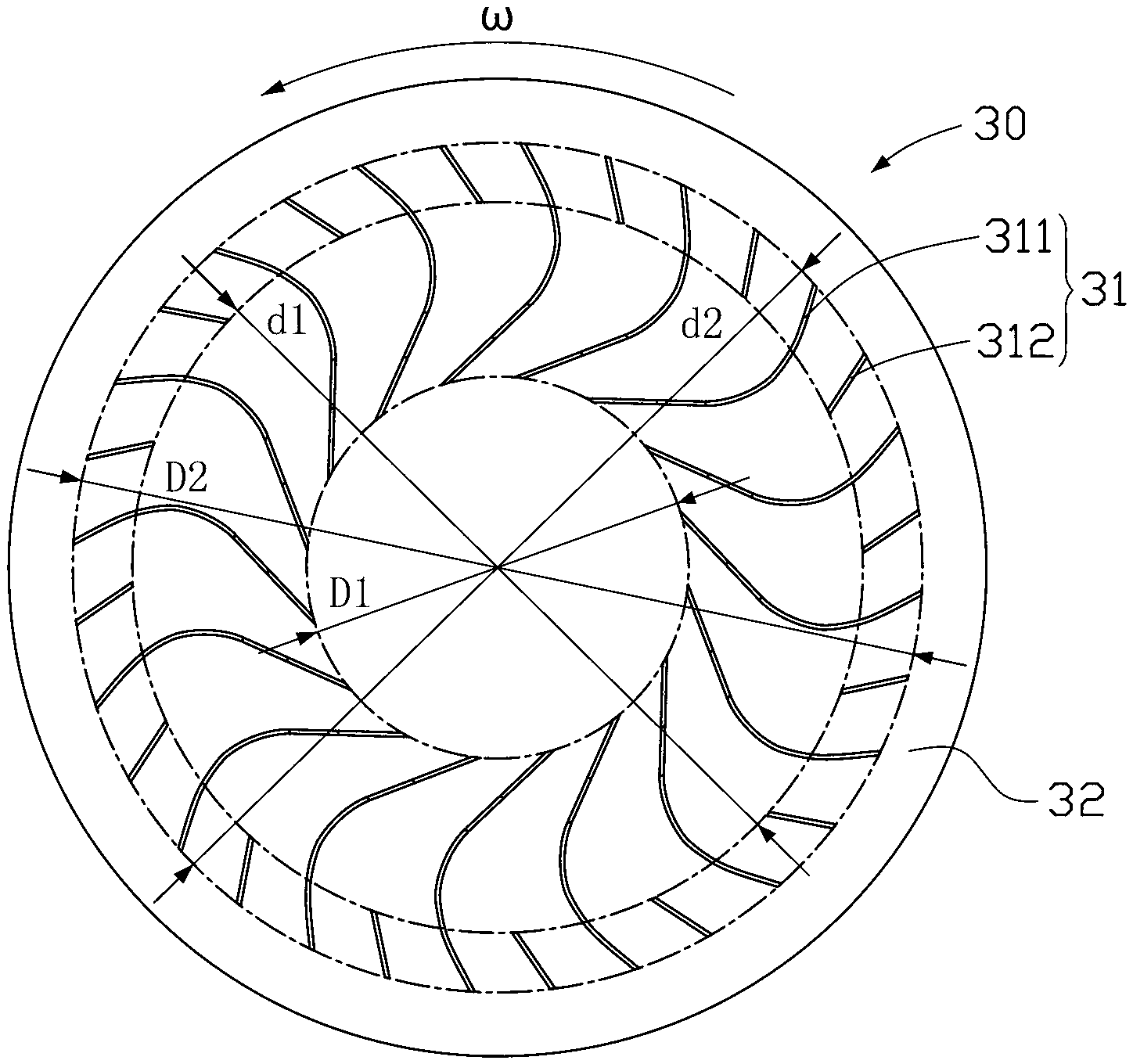
[0031] figure 2 is a schematic structural view of the centrifugal fan provided by the first embodiment of the present invention, image 3 It is a structural schematic diagram of the centrifugal fan impeller provided by the first embodiment of the present invention, please refer to figure 2 and image 3 The centrifugal fan includes a casing 20 and an impeller 30 arranged in the casing 20. The casing 20 is provided with an air inlet 21 and an air outlet 22. The air inlet 21 is set corresponding to the axial center of the centrifugal fan, and the air outlet 22 corresponds to the centrifugal fan. The circumferential tangential position is set, and the air inlet 21 is perpendicular to the air outlet 22.

[0032] The impeller 30 is arra...


PUM


Abstract

The embodiment of the invention discloses a centrifugal fan impeller, comprising an upper blade disc, a lower blade disc and a plurality of blades connected between the upper blade disc and the lower blade disc, wherein the blades comprise a plurality of long blades and a plurality of short blades; the long blades and the short blades are alternatively distributed in the circumferential direction surrounding the impeller; the short blades are arranged at the positions of a flow channel close to outlets of the adjacent long blades; and the blade profile of each long blade adopts a line-arc-line form, and comprises an outlet-end line part, an inlet-end line part and an arc part connected between the outlet-end line part and the inlet-end line part. The embodiment of the invention has the advantages that due to the design that the line-arc-line blade profiles of the long blades are matched with the flow-distributing short blades, the resistance coefficient in the impeller is reduced, meanwhile the pressure of negative pressure areas of the long blades is increased, the vortex formed by the airflow is restrained, and the total efficiency of a fan is improved, so that the flow and the total pressure increase of the fan meet the requirements for high pressure and large flow needed by a snow blowing vehicle.

Description

technical field [0001] The invention relates to the technical field of fans; in particular, it relates to a centrifugal fan and an impeller structure that can be used for a snow blower. Background technique [0002] The snow blower is a sanitation machinery product that uses high-speed, high-pressure airflow to clear snow from roads and other public places. The airflow required by the snow blower is provided by a fan. Therefore, the fan that provides air volume for the snow blower is one of the key components of the snow blower, and the research on the fan for the specific working condition of the snow blower is still in its infancy. [0003] The fan is the core component of the snow blower. The snow blower uses the fan to inject a large amount of high-pressure cold air through the pipeline structure and the nozzle at high speed, so that the nearby snow is blown away to achieve the purpose of snow removal at the airport or on the road. The design of the fan system directly ...

Claims


Application Information

Patent Timeline
Patent Type & Authority Applications(China)
IPC IPC(8): F04D29/28F04D29/30
Inventor 张斌滕新科张劲肖庆麟彭林斌姜方宁李亮彭旭卜伟
Owner ZOOMLION ENVIRONMENTAL IND CO LTD
Why Eureka
Try Eureka