Impulse test system of hydraulic hose

A hydraulic hose and pulse test technology, which is applied in fluid pressure actuation system testing, fluid pressure actuation devices, mechanical equipment, etc., can solve the problems of high cost, unfavorable popularization, high energy consumption, etc., and avoid the failure of the charge pump The effect of using, reducing system energy consumption and reducing cost

Inactive Publication Date: 2013-04-03
ZHEJIANG UNIV
View PDF11 Cites 27 Cited by
  • Summary
  • Abstract
  • Description
  • Claims
  • Application Information

AI Technical Summary

Problems solved by technology

At the same time, because the hydraulic hose pulse test involves a high-pressure, large-flow hydraulic loading system, the curren

Method used


Image

  • Impulse test system of hydraulic hose
  • Impulse test system of hydraulic hose

Examples


Embodiment 1

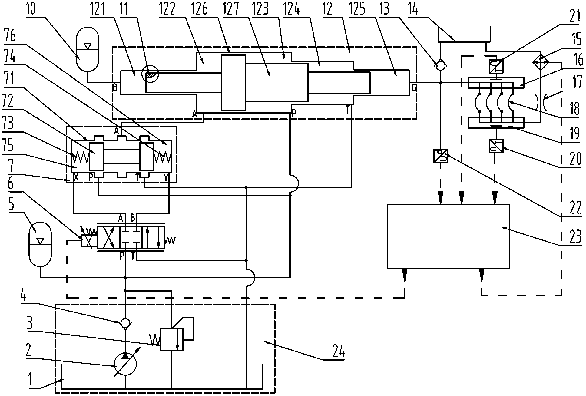
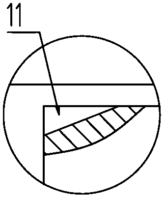
[0020] Embodiment 1, figure 1 and figure 2 A hydraulic hose pulse test system is given; it includes a hydraulic pulse loading system, a temperature control system, a tested hydraulic hose connection block I16, a tested hydraulic hose connection block II19 and a controller 23.

[0021] The hydraulic pulse loading system described above includes oil source 24, hydraulic control valve 7, electro-hydraulic servo valve 6, booster cylinder 12, accumulator I5 and accumulator II10; oil source 24 includes main oil tank 1, hydraulic pump 2 , Relief valve 3 and one-way valve I4; hydraulic pump 2 can discharge pressure oil to provide hydraulic energy for the system; one-way valve I4 is used to ensure that oil can only flow from hydraulic pump 2 to the system, and not reverse flow. The relief valve 3 is used to limit the maximum pressure of the oil source 24 .

[0022] The hydraulic pump 2 is a variable displacement pump or a combination of quantitative pumps; the combination of quantit...


PUM


Abstract

The invention discloses an impulse test system of a hydraulic hose. The system comprises a hydraulic impulse loading system and the like. The hydraulic impulse loading system comprises an oil source and the like. The oil source comprises a main oil tank and the like. The main oil tank is respectively connected with a hydraulic pump and an overflow valve. The hydraulic pump is connected with a one-way valve I which is respectively connected with a hydraulic control valve, an electro-hydraulic servo valve, a pressurizing cylinder and an energy storage device I. The electro-hydraulic servo valve is connected with the hydraulic control valve, and an energy storage device II, the hydraulic control valve and a tested hydraulic hose connecting block I are connected with the pressurizing cylinder. The pressurizing cylinder, the electro-hydraulic servo valve, the hydraulic control valve and the overflow valve are connected with the main oil tank. A temperature control system comprises a throttling hole, a one-way valve II, a high temperature oil tank and a radiator. A tested hydraulic hose connecting block II and the radiator are connected with the throttling hole. The radiator is communicated with the high temperature oil tank. A one-way valve II is connected with the high temperature oil tank, and the one-way valve II is communicated with the tested hydraulic hose connecting block I. The electro-hydraulic servo valve is connected with a controller.

Description

technical field [0001] The invention relates to a hydraulic hose test system, in particular to an energy-saving hydraulic hose pulse test system capable of high temperature tests. Background technique [0002] Hydraulic hoses are widely used in hydraulic systems. During the operation of the hydraulic system, hydraulic hoses are often damaged or failed due to hydraulic pulses or heat. Therefore, the hydraulic hoses are tested to simulate various hydraulic pulses and high temperature phenomena in actual working conditions. For It is of great significance to ensure the safe operation of the hydraulic system. At the same time, because the hydraulic hose pulse test involves a high-pressure, large-flow hydraulic loading system, the current hydraulic hose pulse test system generally consumes a lot of energy and is expensive, which is very unfavorable for popularization. Contents of the invention [0003] The technical problem to be solved by the invention is to provide a hydrau...

Claims


Application Information

Patent Timeline
IPC IPC(8): F15B19/00
Inventor 满在朋丁凡邓民胜丁川刘硕何冰亮
Owner ZHEJIANG UNIV
Why Eureka
Try Eureka