Air dehumidification unit and process

An air dehumidification and air technology, applied in space heating and ventilation, space heating and ventilation details, heating methods, etc., can solve the problem of uneven heating of the inner wall of the hose, narrowing the diameter of the hose, and reducing the internal volume of the hose And other issues

Inactive Publication Date: 2013-04-03
HANON SYST
View PDF13 Cites 0 Cited by
  • Summary
  • Abstract
  • Description
  • Claims
  • Application Information

AI Technical Summary

Problems solved by technology

The disadvantage of this discharge hose construction is that, due to the heating device, a narrowed hose diameter and a reduced internal volume of the hose are produced
Moreover, the heating device only covers a part of the inner wall of the hose, so that the inner wall of the hose is heated unevenly

Method used


Image

  • Air dehumidification unit and process

Examples


Embodiment Construction

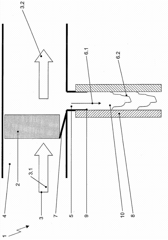
[0026] figure 1 A section is shown of a motor vehicle HVAC system with an air dehumidification unit 1 in the region of the evaporator 2 for supplying heat from the air to be conditioned 3.1 inside the vehicle to the refrigerant of the heat pump system. The evaporator 2 is located in the air flow channel 4 , so that the incoming fresh air 3 . 1 or recirculation air 3 . 1 has to pass through the evaporator 2 . The air 3.1 to be conditioned passes through the evaporator 2, for example at a temperature of 15° C. and a relative humidity of 80%, after passing through the evaporator 2 the dehumidified air has, for example, a relative humidity of 97% and a temperature of 3° C. In the region of the gas flow channel 4 downstream of the evaporator 2 , a vertically (vertical) oriented condensate drain channel 5 is arranged so that the liquid condensate 6 . 1 can flow downwards. A condensate drain channel 5 (drain) is provided for draining of the HVAC system. about figure 1 In the illus...


PUM


Abstract

The invention relates to an air dehumidification unit and process for an HVAC system of a motor vehicle and, more particularly to an air dehumidification unit for an HVAC system of a motor vehicle which is capable of combined refrigeration system and heat pump operation. The motor vehicle HVAC system comprises a heat pump system with a refrigerant-based heating heat exchanger and an evaporator for supplying heat from air to be conditioned for an interior of the motor vehicle to the refrigerant passed in a circuit. The air dehumidification unit includes the following components: an air flow channel, in that the evaporator is located, for passing the air to be conditioned over the evaporator; a vertically oriented condensate water drainage channel branching off at a bottom side of the air flow channel for removing water condensed at the evaporator from the air to be conditioned; and a heating device that either is integrated into a wall of the condensate water drainage channel or is placed outside the condensate water drainage channel adjacent the condensate water drainage channel such that the heating device is capable to heat the internal volume of the condensate water drainage channel from the exterior.

Description

technical field [0001] The present invention relates to an air dehumidification unit for a motor vehicle HVAC system for combined refrigeration system and heat pump operation. Furthermore, the invention relates to a method for dehumidifying air to be conditioned in a passenger compartment using such an air dehumidification unit in a motor vehicle HVAC system operating as a heat pump. Background technique [0002] Until now, HVAC systems were generally used at ambient temperatures above 0°C. Efficient heating is essential in hybrid and / or fully electric vehicles. For this purpose, heat pump systems were researched and developed. For reasons of efficiency, the system's refrigerant circuit operates in air recirculation mode or partial air recirculation mode and also at cold ambient temperatures, thus requiring dehumidification of the air before reheating it, especially between seasons the transitional period between. [0003] According to DE 10163607A1, a HVAC system for mo...

Claims


Application Information

Patent Timeline
Patent Type & Authority Applications(China)
IPC IPC(8): F24F1/00F24F13/22F24F11/02
CPCB60H1/3233F24F3/1405F24F2003/1446F24F2013/227
Inventor M·格拉夫T·哈斯U·福克
Owner HANON SYST
Why Eureka
Try Eureka