
Turning and drying device for battery shell

A technology for drying equipment and battery casings, which is applied in the direction of drying solid materials, drying gas arrangement, non-progressive dryers, etc. It can solve the problems of affecting the drying quality and production efficiency, high labor intensity, and chaotic direction of water placement. Achieve the effect of facilitating sufficient drying, improving drying quality and speeding up drying speed

Inactive Publication Date: 2017-06-13
陈萍
View PDF0 Cites 7 Cited by
  • Summary
  • Abstract
  • Description
  • Claims
  • Application Information

AI Technical Summary

Problems solved by technology

The main problem with this structure is that when the battery case is dehydrated, a lot of dry battery cases that need to be dehydrated must be packed in a mesh bag and placed on the tray, and then the motor is started to drive the battery case to rotate at a high speed on the tray. The centrifugal force of the rotation shakes off the water inside and outside the shell and falls into the dehydration cylinder. During the dehydration process, the net bag must be turned and shaken manually to discharge the water in the shell to the maximum extent.
Not only is the labor intensity high, but also the moisture in some shells is not easy to be thrown out due to the chaotic placement direction, and it has to be screened to pick out the products with moisture in the shell and dry them again, which affects the drying quality and production efficiency

Method used


Image

  • Turning and drying device for battery shell
  • Turning and drying device for battery shell
  • Turning and drying device for battery shell

Examples


Embodiment Construction

[0020] The technical solution of this patent will be further described in detail below in conjunction with specific embodiments.

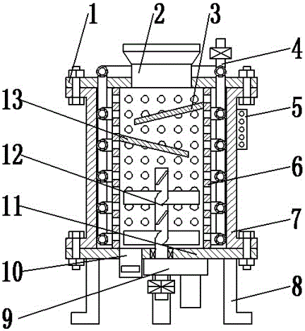
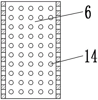
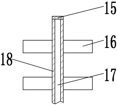
[0021] see Figure 1-5 , a kind of drying equipment for battery casing, comprising a tank body 7; the tank body 7 is set as a hollow cylinder at both ends, the top opening is provided with an upper cover 1, and the bottom opening is provided with a bottom cover 11; the upper The cover 1 and the bottom cover 11 are fixedly connected with the tank body 7 through the mutual screwing of bolts and nuts, and a sealing ring is provided at the joint; the upper cover 1, the tank body 7 and the bottom cover 11 are all made of stainless steel; the upper cover 1 A feed pipe 2 is provided; the feed pipe 2 is welded and fixed on the middle part of the upper cover 1, and the opening of the feed pipe 2 is provided with a threaded cover; the middle part of the tank body 7 is provided with an air guide tube 6; Hollow cylinder, made of stainless steel, the top is we...


PUM


Abstract

The invention provides a battery shell turning and drying equipment, which comprises a tank body; an upper cover is arranged at the top opening of the tank body, and a bottom cover is arranged at the bottom opening of the tank body; an air guide cylinder is arranged in the middle of the tank body; There are a first material guide plate, a second material guide plate and a material turning device; the first material guide plate and the second material guide plate are welded and fixed on the top of the air guide tube; the material turning device is arranged at the bottom of the air guide tube, and the turning The material device is composed of a rotating shaft and a turning plate; the inside of the rotating shaft is provided with a gas flow channel, and the bottom of the rotating shaft is connected with the dehumidifying and driving device; the dehumidifying and driving device is composed of a transmission box, a driving motor, an air extraction pipe and It is composed of an exhaust fan; a drying device is arranged between the inner wall of the tank and the outer wall of the air guide tube; the present invention uses a turning plate to turn the battery case through the setting of the dehumidification and driving device and the turning device, which is convenient for the battery case and heat Air contact is beneficial to improve the dry quality of the battery case.

Description

technical field [0001] The invention relates to a battery processing device, in particular to a material turning and drying device for a battery case. Background technique [0002] At present, the battery shell dehydrator that dehydrates the dry battery shell after cleaning has a structure that a motor is installed on one side of the bottom of a vertical dehydration cylinder, and a commutator is used on the motor shaft extending into the cylinder to move toward the middle of the cylinder. A rotating shaft is installed along the center of the circle, and a mesh bag tray is installed in the gap between the upper end of the rotating shaft and the circumference of the cylinder wall. A motor foot switch is installed on the outer wall of the bottom of the dehydration cylinder. a drainpipe. The main problem with this structure is that when the battery case is dehydrated, a lot of dry battery cases that need to be dehydrated must be packed in a mesh bag and placed on the tray, and ...

Claims


Application Information

Patent Timeline
Patent Type & Authority Applications(China)
IPC IPC(8): F26B11/14F26B21/00F26B25/00
CPCF26B11/14F26B21/001F26B25/00
Inventor 王爽
Owner 陈萍
Learn More