Strip steel drying device

A technology of drying device and strip steel, applied in drying, dryer, drying gas arrangement and other directions, to achieve the effects of large power consumption, improved efficiency and reduced quantity

Active Publication Date: 2014-06-04
湖北大帆金属制品有限公司
View PDF10 Cites 15 Cited by
  • Summary
  • Abstract
  • Description
  • Claims
  • Application Information

AI Technical Summary

Problems solved by technology

[0007]1. The structure is relatively complex, requiring a large number of blowing pipe groups
[0008]2. Low utilization rate of hot air and high power consumption
[0009]3. Drying only by purging structure leads to poor drying effect, and cannot effectively dry the moisture on the surface of the strip, especially the electric furnace drying equipment
[0010]4. There are many and complicated air pipelines, and most of the existing equipment is open structure, resulting in loud noise during the drying process, especially the steam drying equipment

Method used


Image

  • Strip steel drying device

Examples


Embodiment Construction

[0026] In order to make the object, technical solution and advantages of the present invention clearer, the implementation manner of the present invention will be further described in detail below in conjunction with the accompanying drawings.

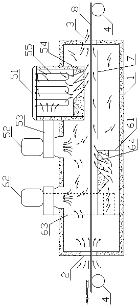
[0027] see figure 1, the embodiment of the present invention provides a strip steel drying device, the strip steel drying device includes a box body 1, at least one set of heating structures in the box body 1, and openings on the front and rear side walls of the box body 1 for the strip steel 8 to enter and exit The strip outlet 2 (also serves as the air inlet) and the strip inlet 3 (also serves as the water vapor outlet). Wherein, the heating structure includes a first guide box 51 , a second guide box 61 , a first circulation fan 52 , a second circulation fan 62 , a first air duct 53 , a second air duct 63 , a heater 55 and the like. The first diversion box 51, the first circulating fan 52, the first air channel 53 and the heater 5...


PUM


Abstract

The invention discloses a strip steel drying device, and belongs to the technical field of drying devices. The strip steel drying device comprises a box, a heating structure, a strip steel outlet and a strip steel inlet. The heating structure comprises a first flow guiding box, a second flow guiding box, a first circulating fan, a second circulating fan, a first air channel, a second air channel and a heater, wherein the first flow guiding box is arranged over strip steel, the second flow guiding box is arranged under the strip steel, the heater is arranged in the first flow guiding box, an air inlet of the first flow guiding box is communicated with the air outlet end of the first circulating fan through the first air channel, a first purging structure is arranged on the side, close to the strip steel, of the first flow guiding box, the air draft end of the first circulating fan is communicated with the box (1), an air inlet of the second flow guiding box is communicated with the air outlet end of the second circulating fan through the second air channel, a second purging structure is arranged on the side, close to the strip steel, of the second flow guiding box, the air draft end of the second circulating fan is communicated with the box, the second purging structure carries out forward air outlet, and the included angle between the air outlet direction of the second purging structure and the strip steel ranges from 30 degrees to 45 degrees.

Description

technical field [0001] The invention relates to the technical field of drying equipment, in particular to a strip steel drying device, in particular to a strip steel drying device with high efficiency, low energy consumption, low noise and simple structure. [0002] Background technique [0003] In the process steps of cold-rolled strip steel, the first link is to carry out shelling, pickling, neutralization, cleaning and drying processes on the hot-rolled strip steel. In the drying process, steam drying and electric furnace drying are mostly used at present. Steam drying and electric furnace drying equipment usually consist of a box body, at least one set of heating structures in the box body, and strip steel outlets and strip steel inlets for strip steel entry and exit on the front and rear side walls of the box body. The heating structure usually consists of structures such as heaters, fans and multiple air lines. [0004] For example, the patent application No. 2009202...

Claims


Application Information

Patent Timeline
Patent Type & Authority Applications(China)
IPC IPC(8): F26B21/00F26B13/02
Inventor 宁大勇梁文兴
Owner 湖北大帆金属制品有限公司
Why Eureka
Try Eureka