Multi-stage composite steam dehydration structure and heat accumulator

A dehydration structure and steam technology, applied in chemical instruments and methods, dispersed particle separation, separation methods, etc., can solve problems such as "water hammer" and steam with water, so as to improve steam dryness, reduce effluent loss, and reduce The effect of safety hazards

Pending Publication Date: 2020-04-03
BEIJING JINGCHENGKELIN ENVIRONMENTAL PROTECTION TECH +1
View PDF0 Cites 0 Cited by
  • Summary
  • Abstract
  • Description
  • Claims
  • Application Information

AI Technical Summary

Problems solved by technology

[0004] The purpose of the present invention is to provide a multi-stage composite steam dehydration structure and a heat accumulator to solve the problem of steam carrying water in the heat accumulator system and to avoid the phenomenon of "water hammer"

Method used


Image

  • Multi-stage composite steam dehydration structure and heat accumulator
  • Multi-stage composite steam dehydration structure and heat accumulator
  • Multi-stage composite steam dehydration structure and heat accumulator

Examples


Embodiment approach 1

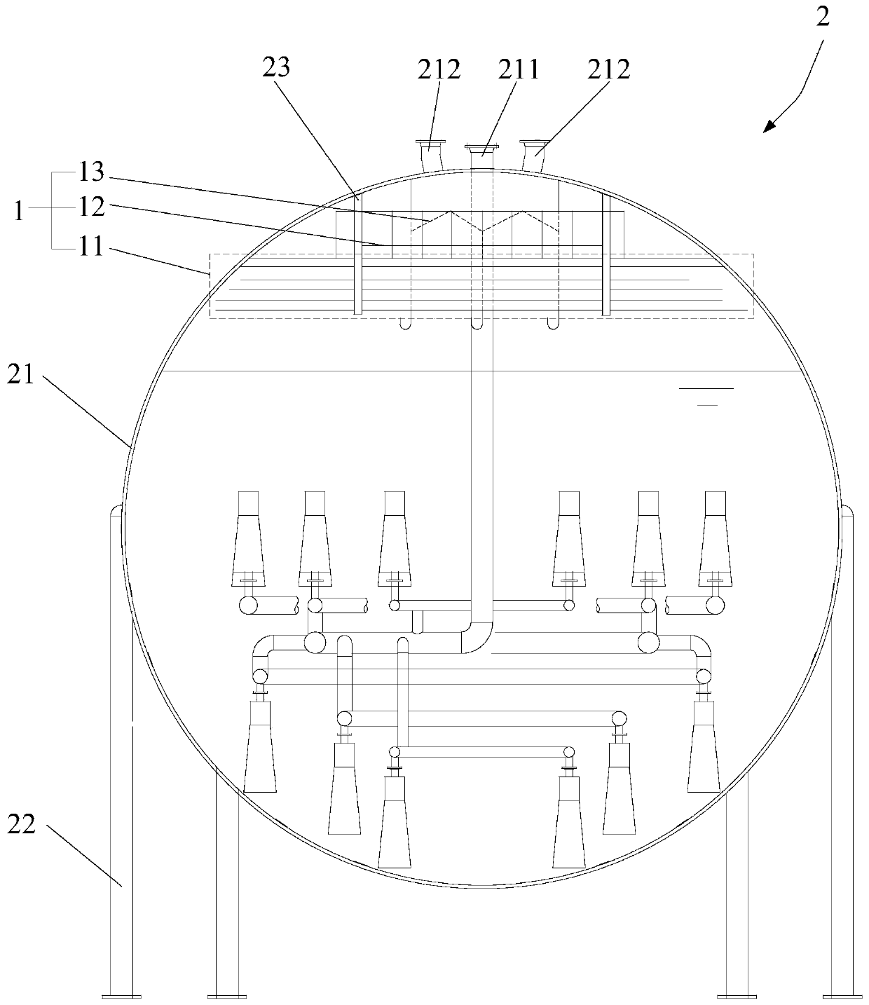
[0033] The present invention provides a multi-stage composite steam dehydration structure 1, please refer to Figure 1 to Figure 8 , The multi-stage composite steam dehydration structure 1 includes a primary dehydration element 11 , a secondary dehydration element 12 and a tertiary dehydration element 13 .

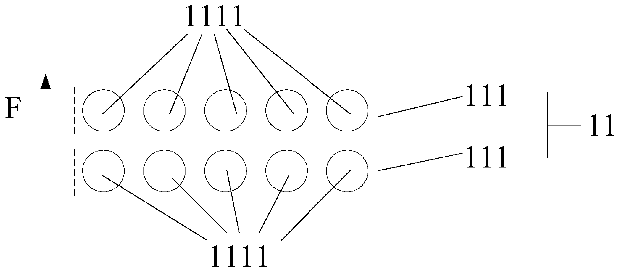
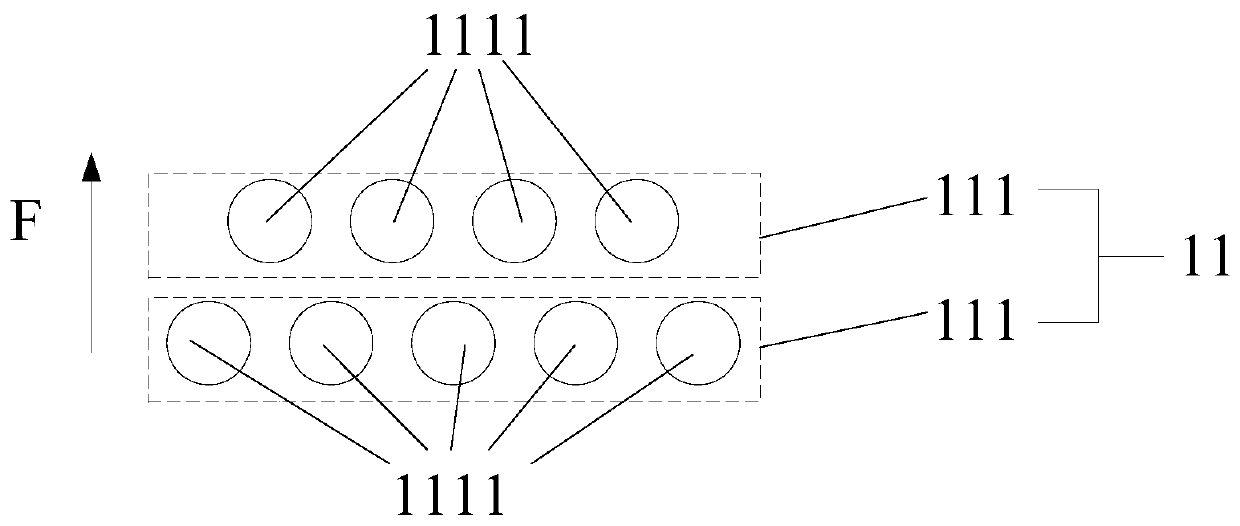
[0034] Specifically, the primary dewatering element 11 has multi-layer close-packed tube bundles 111 arranged at intervals along the first direction F, and each layer of close-packed tube bundles 111 has a plurality of tube bodies 1111 arranged side by side; 11, the secondary dewatering part 12 has a plurality of corrugated plates 121 arranged at intervals along the horizontal direction; the tertiary dewatering part 13 is located above the secondary dewatering part 12, and the tertiary dewatering part 13 is connected by a plurality of bending holes The plate 131 is formed, and the bent orifice plate 131 is provided with a perforation 1313 .

[0035] The multi-stage compos...

Embodiment approach 2

[0059] The present invention provides a heat accumulator 2, please refer to figure 1 , the heat accumulator 2 includes a tank body 21 and a multi-stage composite steam dehydration structure 1 . Wherein, the top of the tank body 21 is provided with a steam inlet pipe 211 and at least one steam outlet pipe 212, and the steam inlet pipe 211 can extend into the lower inner cavity of the tank body 21; In the upper inner cavity, and located below at least one steam outlet pipe 212. The specific structure, working principle and beneficial effects of the multi-stage composite steam dehydration structure 1 in this embodiment are the same as those in Embodiment 1, and will not be repeated here.

[0060] The regenerator 2 is equipped with a multi-stage composite steam dehydration structure 1 inside, and the water droplets carried by the wet saturated steam are filtered out in the inner cavity of the tank body 21 through multi-stage filtration, thereby increasing the dryness of the steam...


PUM


Abstract

The invention discloses a multi-stage composite steam dehydration structure and a heat accumulator. The multi-stage composite steam dehydration structure comprises: a first-stage dehydration member having a plurality of layers of densely arranged tube bundles arranged at intervals along a first direction, wherein each layer of densely arranged tube bundles having a plurality of tube bodies arranged side by side; a second-stage dehydration member which is located above the first-stage dehydration member, and is provided with a plurality of corrugated plates which are arranged at intervals in the horizontal direction; a third-stage dehydration member which is located above the second-stage dehydration member, and is composed of a plurality of bent pore plates which are connected with one another, wherein through holes are formed in the bent pore plates. According to the multi-stage composite steam dehydration structure, steam is subjected to three times of water drop filtering through the first-stage dehydration member, the second-stage dehydration member and the third-stage dehydration member, so that the dryness of the steam is improved, and the potential safety hazard of a water hammer phenomenon of the steam is reduced.

Description

technical field [0001] The invention relates to the technical field of waste heat steam utilization, in particular to a multi-stage composite steam dehydration structure and a heat accumulator. Background technique [0002] The domestic conventional horizontal heat accumulator does not have a steam dehydration device at the steam outlet. The heat storage and heat release of the heat accumulator are realized by the pressure change of high-pressure saturated water and saturated steam in the heat accumulator. When the heat is released, the flash steam The steam directly enters the external steam pipe network through the heat release pipe. [0003] The wet saturated steam generated by the heat release of the accumulator, the wet steam with water enters the pipe network, and there is a potential safety hazard of the "water hammer" phenomenon. "Water hammer" is also called water hammer, which is a phenomenon caused by the presence of steam and water in the pipeline, and the speed...

Claims


Application Information

Patent Timeline
Patent Type & Authority Applications(China)
IPC IPC(8): B01D45/08B01D45/10B01D53/26
CPCB01D45/08B01D45/10B01D53/26
Inventor 杨明华杨源满李睿井小海
Owner BEIJING JINGCHENGKELIN ENVIRONMENTAL PROTECTION TECH
Why Eureka
Try Eureka