
Acrylonitrile quenching device and process

An acrylonitrile and process technology, which is applied in the field of acrylonitrile synthesis, can solve the problems such as the inability to effectively solve the uneven flow field, reduce the ammonia absorption efficiency, increase the loss of acrylonitrile, etc., so as to reduce the amount of discharged wastewater and increase the gas-liquid contact area. , the effect of reducing efflux loss

Pending Publication Date: 2022-07-29
上海盛蓝汇科技有限责任公司
View PDF3 Cites 0 Cited by
  • Summary
  • Abstract
  • Description
  • Claims
  • Application Information

AI Technical Summary

Problems solved by technology

The patent also has no flow stabilization measures, which cannot effectively solve the problem of uneven flow field; and although the lower section of the empty tower structure avoids the clogging problem of the lower section, the upper plate tray still cannot avoid the clogging problem, which affects the gas-liquid flow field in the tower. Reduce the absorption efficiency of ammonia and increase the loss of acrylonitrile

Method used


Image

  • Acrylonitrile quenching device and process
  • Acrylonitrile quenching device and process

Examples


Embodiment 1

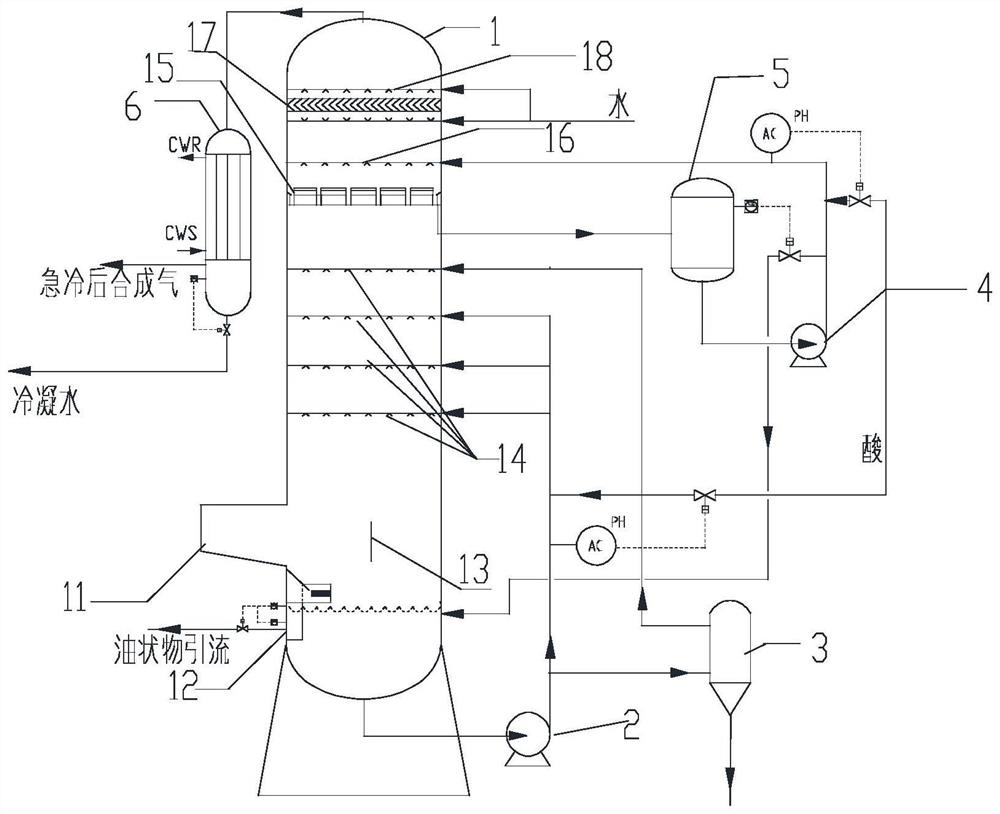
[0077] The composition of the reactor off-gas, the dust content, and the acid absorbent were the same as those of Comparative Example 1. The feed temperature is 220°C, and the quenching technology of the present invention is adopted. The structure of the quenching tower is as follows: the upper and lower sections are empty towers, the first-level spraying of the lower section is provided with 5 layers of sprays, the distance between the spray layers is 1 meter, and the upper section is provided with 2 layers of sprays, The spacing between the spray layers is 1 meter. The spray density and spray particle size of the first-level spray from bottom to top are: (1) the spray density is 500%, the spray particle size is 200μm, (2) the spray density is 400%, and the spray particle size is 300μm , (3) spray density 300%, spray particle size is 500μm, (4) spray density 300%, spray particle size is 500μm, (5) spray density 300%, spray particle size is 800μm. The solid content of the pri...

Embodiment 2

[0079] Reactor tail gas composition and dust content, and acid absorbent are the same as in Example 1. The feed temperature is 210°C, and the quenching technology of the present invention is adopted. The structure of the quenching tower is as follows: the upper and lower sections are empty towers, the first-level spray in the lower section is provided with 4 layers of sprays, the distance between the spray layers is 1 meter, and the upper section is provided with 2 layers of sprays. The spacing between the spray layers is 1 meter. The spray density and spray particle size of the first-level spray from bottom to top are: (1) the spray density is 600%, the spray particle size is 200μm, (2) the spray density is 500%, and the spray particle size is 300μm , (3) the spray density is 400%, the spray particle size is 500 μm, (4) the spray density is 400%, and the spray particle size is 800 μm. The solid content of the primary spray circulating fluid is reduced by 15% bypass desolidif...

Embodiment 3

[0081] Reactor tail gas composition and dust content, and acid absorbent are the same as in Example 1. The feed temperature is 210°C, and the quenching technology of the present invention is adopted. The structure of the quenching tower is as follows: the upper and lower sections are empty towers, the first-level spray in the lower section is provided with 5 layers of sprays, the distance between the spray layers is 1 meter, and the upper section is provided with 2 layers of sprays. The spacing between the spray layers is 1 meter. The spray density and spray particle size of the first-level spray from bottom to top are: (1) the spray density is 600%, the spray particle size is 200μm, (2) the spray density is 400%, and the spray particle size is 500μm , (3) spray density of 400%, spray particle size of 500μm, (4) spray density of 400%, spray particle size of 500μm, (5) spray density of 300%, spray particle size of 1000μm. The solid content of the primary spray circulating flui...


PUM


Abstract

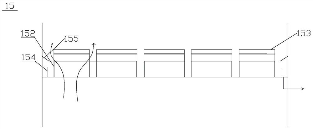
The invention relates to an acrylonitrile quenching device and process. The device comprises a quench tower, a first-stage spraying layer, a rising gas liquid receiving disc and a second-stage spraying layer are sequentially arranged in the tower from bottom to top, vent holes are formed in the rising gas liquid receiving disc, a process gas inlet is formed in the lower portion of the quench tower, and a rectifying plate is arranged in the tower corresponding to the process gas inlet; the first-stage absorption liquid external circulation comprises a first-stage pipeline which is communicated with tower kettle feed liquid and a first-stage spraying layer, the first-stage pipeline is connected with a first-stage circulating pump and a liquid-solid separation system on at least one shunting branch, and the liquid-solid separation system is used for discharging concentrated wastewater; and the second-stage absorption liquid external circulation comprises a second-stage pipeline which is communicated with the gas rising and liquid receiving disc and the second-stage spraying layer, and the second-stage pipeline is sequentially connected with a buffer tank and a second-stage circulating pump. According to the invention, the gas flow field in the tower is optimized, the gas-liquid mass transfer efficiency is improved, the ammonia absorption efficiency and the dust removal efficiency are improved, the acrylonitrile side reaction loss and the discharge loss are reduced, the acrylonitrile quenching yield is improved, and the blockage probability of the quenching tower and the subsequent process is reduced.

Description

technical field [0001] The invention belongs to the technical field of acrylonitrile synthesis, in particular to an acrylonitrile quenching device and a process. Background technique [0002] Acrylonitrile is an important chemical raw material for the three major synthetic materials fiber, rubber and plastic. It is mainly used to produce polyacrylonitrile fiber, acrylic fiber, ABS resin, acrylamide, adiponitrile, carbon fiber, etc. The mainstream advanced production technology of acrylonitrile is propylene fluidized bed ammoxidation process. [0003] The process gas obtained from ammoxidation of propylene contains propionitrile, acetone, acrolein, acetaldehyde, acetic acid, oligomer, CO, in addition to the main product acrylonitrile, by-product acetonitrile and hydrocyanic acid. 2 , impurities such as CO, and excess NH 3 , a small amount of broken catalyst solid particles, etc. [0004] After the high temperature acrylonitrile process gas is cooled to about 210 ℃ through ...

Claims


Application Information

Patent Timeline
Patent Type & Authority Applications(China)
IPC IPC(8): F28C1/02F28F25/06C07C253/34C07C255/08
CPCF28C1/02F28F25/06C07C253/34C07C255/08
Inventor 马洪玺张文军
Owner 上海盛蓝汇科技有限责任公司
Learn More