Hydrodynamic cavitation reactor

A reactor and post-stage technology, applied in the field of wastewater treatment equipment, can solve the problems of low cavitation effect and less OH, and achieve the effects of low energy consumption, simple operation, and improved treatment efficiency

Active Publication Date: 2016-04-20
ZHONGBEI UNIV
View PDF7 Cites 24 Cited by
  • Summary
  • Abstract
  • Description
  • Claims
  • Application Information

AI Technical Summary

Problems solved by technology

[0010] However, the current conventional hydraulic cavitation reactors only have a single Venturi tube or orifice cavitation device. This simple cavitation structure produces less OH and has a lower cavitation effect.

Method used


Image

  • Hydrodynamic cavitation reactor
  • Hydrodynamic cavitation reactor
  • Hydrodynamic cavitation reactor

Examples


Embodiment Construction

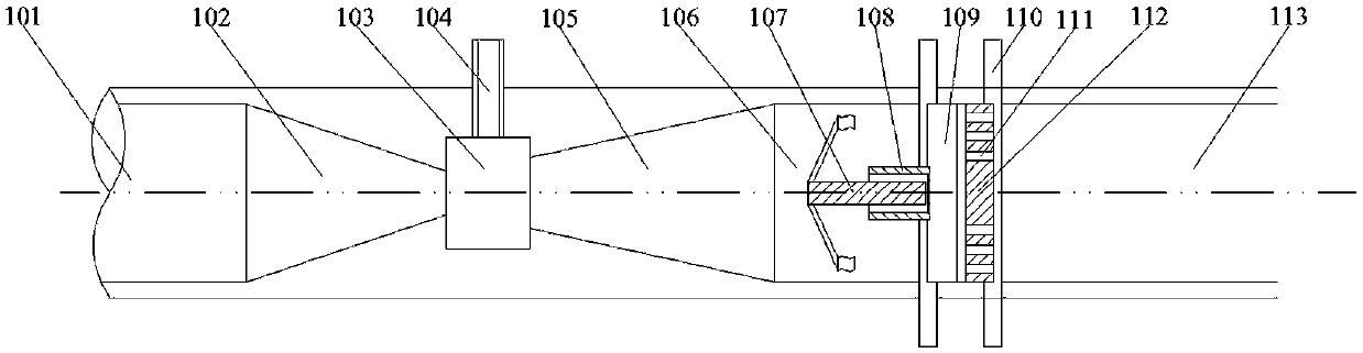
[0027] The specific structure of the hydrodynamic cavitation reactor is as follows: figure 1 As shown, it consists of three parts: the front section of the reactor, the middle section of the reactor and the back section of the reactor, wherein the front section of the reactor and the middle section of the reactor are integrated, and the back section of the reactor is connected to the middle section of the reactor through a flange 110 . A fluid inlet 101 is arranged on the front section of the reactor, and a fluid outlet 113 is arranged on the rear section of the reactor.

[0028] The front section of the reactor is provided with a fluid jet contraction chamber 102, a negative pressure chamber 103 and a fluid jet expansion chamber 105. The expansion port of the fluid jet contraction chamber 102 is connected to the fluid inlet 101, and the contraction port is connected to the negative pressure chamber 103. The negative pressure chamber The other end of 103 is connected to the co...


PUM

PropertyMeasurementUnit
pore sizeaaaaaaaaaa

Abstract

The invention discloses a hydrodynamic cavitation reactor. The hydrodynamic cavitation reactor comprises a reaction front section, a reactor middle section and a reactor rear section, wherein a negative pressure bin, a fluid jet contraction cavity, a fluid jet expansion cavity and an oxidant inlet are arranged in the reactor front section, the fluid jet contraction cavity and the fluid jet expansion cavity are located at two ends of the negative pressure bin, and the oxidant inlet is formed in the upper part of the negative pressure bin; a swirler rotating in the axial direction of the reactor is arranged in a swirling cavity in the reactor middle section; an orifice plate with small holes formed in the surface is arranged in the reactor rear section and is perpendicular to the axial direction of the reactor. The hydrodynamic cavitation reactor generates instant high temperature and high pressure through three-level cavitation effects of first-level jetting, second-level swirling and third-level current limiting to directly degrade organic matters, harmless degradation of conventional organic pollutants difficult to degrade is realized, and the hydrodynamic cavitation reactor can be applied to wastewater treatment in any occasions.

Description

technical field [0001] The invention belongs to the technical field of wastewater treatment equipment, and relates to a hydraulic cavitation reaction device used in industrial wastewater treatment devices. The hydraulic cavitation reaction device of the invention is particularly suitable for the treatment of high-concentration, refractory organic wastewater. Background technique [0002] Water pollution is the biggest problem in the current water environment, especially the persistent refractory organic pollutants in the water environment are widely distributed, stable in nature, and more harmful. For example, polycyclic aromatic hydrocarbons undergo a series of complex processes in the atmosphere or water. The reaction can generate secondary pollutants with stronger carcinogenic activity or mutagenicity, posing a greater threat to human health. Advanced oxidation technology is an effective way to effectively treat such persistent and refractory organic pollutants. [0003]...

Claims


Application Information

Patent Timeline
Patent Type & Authority Applications(China)
IPC IPC(8): C02F1/72
CPCC02F1/72C02F2305/023
Inventor 晋日亚乔怡娜贺增弟孔维甸杨思静
Owner ZHONGBEI UNIV
Why Eureka
Try Eureka