

Sintering flue gas waste heat staged cyclic utilization and pollutant emission reducing process and system
A technology for sintering flue gas and pollutants, applied in waste heat treatment, gas treatment, separation methods, etc., can solve the problem of low utilization rate of waste heat resources of sintering flue gas, failure to consider the influence of flue gas humidity, and zero utilization rate of sintering flue gas and other issues, to achieve the effect of reducing flue gas emission control, improving the efficiency of waste heat utilization, and realizing the effect of waste heat utilization
- Summary
- Abstract
- Description
- Claims
- Application Information
AI Technical Summary
Problems solved by technology
Method used
Image

Examples
specific Embodiment
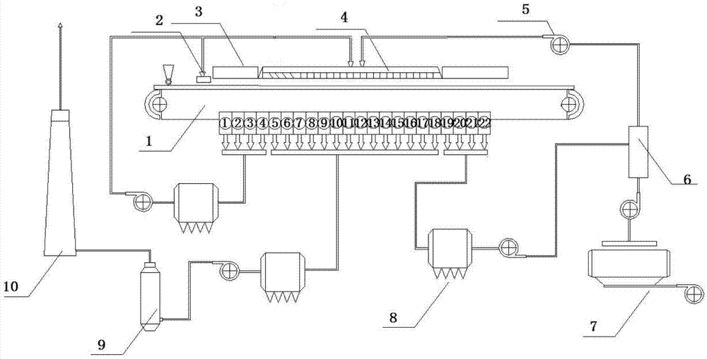
[0044] Such as figure 1 As shown, the system includes a sintering machine 1, ①~④ are bellows for low temperature, high oxygen and low humidity section, ⑤~ It is an air box for the medium temperature, low oxygen and high humidity section, It is a high-temperature, high-oxygen, and low-humidity bellows; the low-temperature, high-oxygen, and low-humidity bellows ① to ④ are connected to the dust removal device and then respectively connected to the ignition furnace 2 of the sintering machine 1 and the sealed hot air cover 4 of the sintering machine 1; the medium-temperature, low-oxygen, and high-humidity Wet section bellows ⑤~ Connect the desulfurization device 9 and the chimney 10 in turn after connecting the dust removal device; the high temperature, high oxygen and low humidity section The dust removal device 8 is first connected and then connected to the sealed hot air hood 4 of the sintering machine 1 through the mixing chamber 6 which is also connected to the cooling m...
PUM
 Abstract
Description
Claims
Application Information