Three-dimensional microwave imaging method for correcting multi-channel amplitude-phase error

A three-dimensional imaging, amplitude and phase error technology, applied in radio wave measurement systems, radio wave reflection/re-radiation, utilization of re-radiation, etc., can solve the problem of direct imaging processing unable to focus imaging

Inactive Publication Date: 2014-07-09
INST OF ELECTRONICS CHINESE ACAD OF SCI
View PDF3 Cites 2 Cited by
  • Summary
  • Abstract
  • Description
  • Claims
  • Application Information

AI Technical Summary

Problems solved by technology

[0005] The purpose of the present invention is to disclose a microwave three-dimensional imaging method for correcting multi-channel amplitude and phase errors, which can correct the amplitude and phase errors of the echo data of the array antenna to obtain a three-dimensional image, so as to solve the problem between multiple transmitting and receiving channels of the array antenna microwave imaging system. Due to the different characteristics of each antenna and the differences in channel amplitude and phase caused by transmission lines and microwave switches in each channel, there is a problem that direct imaging processing cannot focus imaging

Method used


Image

  • Three-dimensional microwave imaging method for correcting multi-channel amplitude-phase error
  • Three-dimensional microwave imaging method for correcting multi-channel amplitude-phase error
  • Three-dimensional microwave imaging method for correcting multi-channel amplitude-phase error

Examples


Embodiment Construction

[0036] Various details involved in the technical solution of the present invention will be described in detail below in conjunction with the accompanying drawings.

[0037] Before proceeding to the specific elaboration of the steps, the important symbols used in the invention will be uniformly explained:

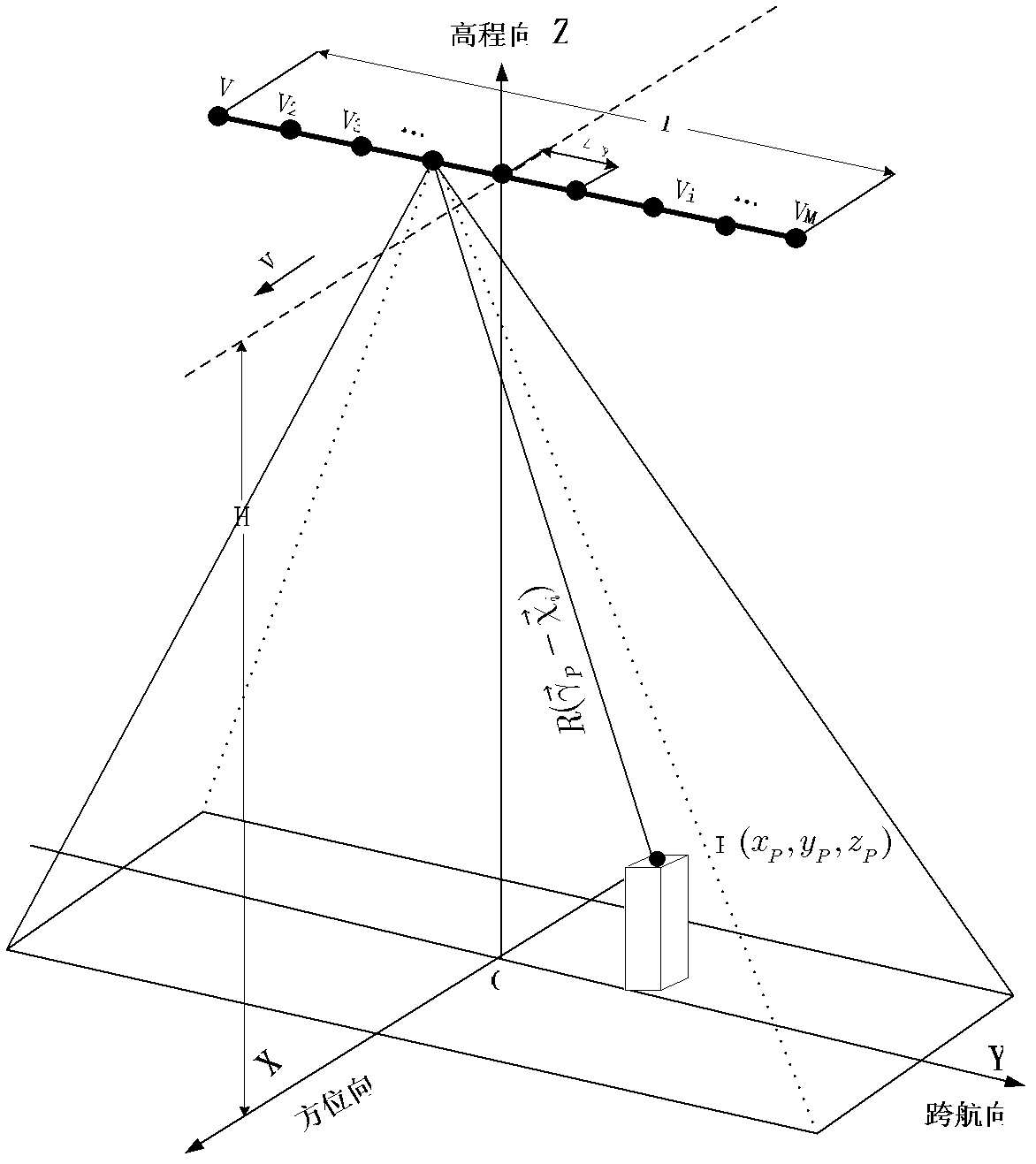
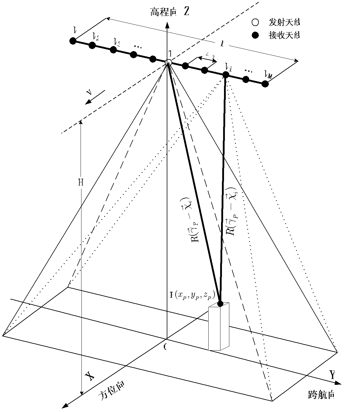
[0038] like figure 1 and image 3 As shown, X, Y and Z represent the rectangular coordinate axes of the three-dimensional space of the imaging target area, wherein the movement direction of the carrier platform of the array antenna microwave three-dimensional imaging system is called the azimuth direction X; the direction perpendicular to the movement direction is defined as the cross-course direction Y; the definition The azimuth direction and the normal direction Z across the course are the elevation direction; when the antenna array is a uniform sending and receiving antenna, it corresponds to the self-sending and self-receiving mode, and the antenna array is set to incl...


PUM


Abstract

A microwave three-dimensional imaging method for correcting multi-channel amplitude and phase errors, involving microwave three-dimensional imaging technology, using a two-dimensional imaging algorithm to obtain a two-dimensional image for the two-dimensional data of each receiving channel in the microwave original three-dimensional echo data; In the method, the scaler target is used as the reference target, and the maximum amplitude value of each channel reference target is used as a reference, and the amplitude correction is performed on all channel data; the actual distance and ideal distance from the reference target to each receiving antenna are obtained as the multi-channel distance offset correction The filter H1(f) of the filter H1(f); use Fourier transform to transform the signal into the range-to-frequency domain, multiply it with the filter, and then use the Fourier inverse transform to transform the signal back to the range-to-time domain; take the peak value of the reference target in each two-dimensional image The unwrapped phase at the position is subtracted from the ideal phase history calculated by the ideal distance, and the multi-channel phase error correction factor H2(i) is obtained; the influence of the phase error is compensated by multiplying H2(i) with the data after two-dimensional imaging; A well-focused 3D image of the target area is obtained using a back-projection algorithm across rows to Y.

Description

technical field [0001] The invention relates to the technical field of microwave three-dimensional imaging, in particular to a microwave three-dimensional imaging method for correcting multi-channel amplitude and phase errors for array antennas. Background technique [0002] Array antenna microwave 3D imaging system is a new microwave 3D imaging technology, such as figure 1 As shown, the imaging system forms a synthetic aperture in the direction of motion (azimuth direction X) through the movement of the carrier platform (such as aircraft, satellite, ground orbit, etc.); ) array antenna, forming an array synthetic aperture; in the propagation direction of the electromagnetic wave, the broadband signal is transmitted and then pulse compressed; the three-dimensional resolution imaging of the observation area / target is realized. [0003] Since the array antenna microwave 3D imaging system is a multi-channel system, there are unpredictable inter-channel amplitude and phase erro...

Claims


Application Information

Patent Timeline
Patent Type & Authority Patents(China)
IPC IPC(8): G01S13/90
CPCG01S13/904
Inventor 王彦平韩阔业谭维贤洪文吴一戎
Owner INST OF ELECTRONICS CHINESE ACAD OF SCI
Why Eureka
Try Eureka