Lead-sealing lock

A keyhole and main body technology, applied in the direction of seals, stamps, instruments, etc., can solve the problems of high cost and inconvenient use, and achieve the effect of simple structure

Inactive Publication Date: 2013-04-03
DALIAN SHENGJUN GARMENT ACCESSORIES
View PDF0 Cites 3 Cited by
  • Summary
  • Abstract
  • Description
  • Claims
  • Application Information

AI Technical Summary

Problems solved by technology

[0002] The lead seals in the prior art require tools to remove the lead seals during use, which is costly and inconvenient to use

Method used


Image

  • Lead-sealing lock

Examples


Embodiment Construction

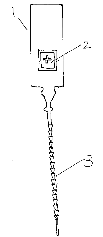
[0008] Such as figure 1 As shown, the present invention includes a lead blockade main body, the lead blockade main body 1 is connected with a lock fringe 3, and the lead blockade main body 1 is provided with a keyhole 2 matched with the lock fringe 3, and the lead blockade main body 1 1. The keyhole 2 and the lock tassel 3 are in one structure. The lock tassel 3 is tooth-shaped. When in use, the tail of the lock tassel 3 can be locked through the keyhole 2. When unloading, the lock tassel 3 Just take it out.

[0009] The above is only a preferred embodiment of the present invention, but the scope of protection of the present invention is not limited thereto. Anyone familiar with the technical field within the technical scope disclosed in the present invention, according to the technical solution of the present invention Any equivalent replacement or change of the inventive concepts thereof shall fall within the protection scope of the present invention.


PUM


Abstract

The invention discloses a lead-sealing lock which comprises a lead-sealing lock body connected with a lock cylinder, wherein a lock hole matched with the lock cylinder is formed on the lead-sealing lock body; the lead-sealing lock body, the lock hole and the lock cylinder are integrally formed; and the lock cylinder is dentiform. The lead-sealing lock has the characteristic of simple structure; the lead-sealing lock can be removed without unlocking tools; the dentiform lock cylinder can be effectively controlled in length; and the use of the lead-sealing lock is more convenient and practicable.

Description

technical field [0001] The invention relates to a lead blockade. Background technique [0002] The lead seal in the prior art needs tools to remove the lead seal during use, which is costly and inconvenient to use. Contents of the invention [0003] The object of the present invention is to overcome above-mentioned insufficient problem, a kind of lead blockade is provided. [0004] The technical solution adopted by the present invention to achieve the above object is: lead blockade, comprising a lead blockade main body, the lead blockage main body is connected with a lock fringe, and the lead blockade main body is provided with a keyhole that matches the lock fringe , the main body of the lead seal, the keyhole, and the lock fringe are all in one structure, and the lock fringe is tooth-shaped. [0005] The present invention is characterized in that the structure is simple, the lead blockage can be removed without an unlocking tool, and the length of the tooth-shaped tass...

Claims


Application Information

Patent Timeline
IPC IPC(8): G09F3/03
Inventor 杨晓军
Owner DALIAN SHENGJUN GARMENT ACCESSORIES
Why Eureka
Try Eureka