Light-emitting element driver circuit

A technology of light-emitting components and driving circuits, which is applied to electrical components, instruments, static indicators, etc., can solve the problems of different critical voltages, uneven light emission of display panels, critical voltage variations, etc., and achieve the effect of eliminating critical voltage variations

Inactive Publication Date: 2013-04-03
WINTEK CORP
View PDF5 Cites 2 Cited by
  • Summary
  • Abstract
  • Description
  • Claims
  • Application Information

AI Technical Summary

Problems solved by technology

The threshold voltage of the drive transistor is determined by the manufacturing process, which often results in a different threshold voltage for each pixel, and the threshold voltage of the drive transistor may also vary during use.
In this way, the display panel of the organic light-emitting diode will not emit light uniformly, or cause the power supply resistance voltage drop (IR drop) of the driving current path to cause brightness changes...etc.

Method used


Image

  • Light-emitting element driver circuit
  • Light-emitting element driver circuit
  • Light-emitting element driver circuit

Examples


Embodiment Construction

[0028] Reference will now be made in detail to the exemplary embodiments of the present invention, examples of which are illustrated in the accompanying drawings. In addition, wherever possible, elements / members using the same reference numerals in the drawings and embodiments represent the same or similar parts.

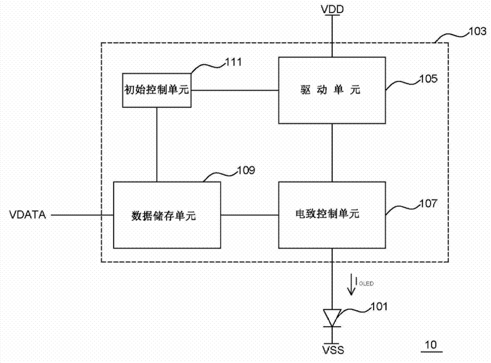
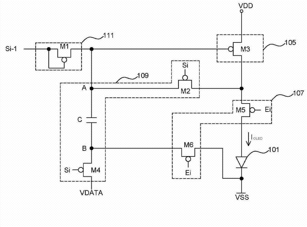
[0029] figure 1 Illustrated as a schematic diagram of an electro-element display device 10 in an electro-element display device according to an exemplary embodiment of the present invention, and Figure 2A shown as figure 1 The implementation circuit diagram of the electro-sensitive element display device 10. Please merge reference figure 1 and Figure 2A , the electroluminescent element display device 10 of this exemplary embodiment includes a light-emitting element 101 (light-emitting component, such as: organic light-emitting diode (OLED), but not limited thereto) and a light-emitting element driving circuit (light-emitting component driving circuit) 103. W...


PUM


Abstract

The invention provides a light-emitting element driver circuit. The light-emitting element driver circuit includes a driver unit for generating a driving current to the light-emitting element; a data storage unit for storing a threshold voltage of the driver unit and current data signal voltage; and a control unit being controlled to be conducted during a light emitting period so that the driver unit generates a driving current in response to the threshold voltage and current data signal voltage stored in the data storage unit.

Description

technical field [0001] The invention relates to a device, in particular to a light-emitting element driving circuit. Background technique [0002] A general organic light emitting diode generates a driving current by controlling the gate and source of its driving transistor, so that the organic light emitting diode emits light. At this time, the critical voltage of the driving transistor will affect the magnitude of the driving current flowing through the organic light emitting diode. The threshold voltage of the driving transistor is determined by the manufacturing process, which often causes the threshold voltage of each pixel to be different, and the threshold voltage of the driving transistor may also vary during use. In this way, the display panel of the organic light-emitting diode will not emit light uniformly, or the power supply resistance voltage drop (IR drop) of the driving current path will cause the brightness to change... and other problems. Contents of the...

Claims


Application Information

Patent Timeline
Patent Type & Authority Applications(China)
IPC IPC(8): G09G3/32
CPCG09G3/3233G09G2300/0819G09G2300/0842G09G2300/0861H05B45/44
Inventor 王文俊廖文堆王宗裕苏国彰
Owner WINTEK CORP
Why Eureka
Try Eureka