High-power LED lamp

a high-power, led lamp technology, applied in semiconductor devices, lighting and heating apparatus, lighting support devices, etc., to achieve the effect of enhancing the heat dissipation capability, stable driving current, and good heat dissipation ability

Inactive Publication Date: 2013-03-19
LO HONHUNG +1
View PDF6 Cites 1 Cited by
  • Summary
  • Abstract
  • Description
  • Claims
  • Application Information

AI Technical Summary

Benefits of technology

[0016]In the high-power LED lamp set, the power converting module, which is located within the power supply casing, comprises circuits with voltage converting, current rectifying and LED driving functions. With these circuits, the converted low-voltage output may be further rectified and regulated to produce a stable driving current. This may solve the problems caused by the sharp forward voltage-current characteristic of LED, that is, prevent the LED from burning up when the input voltage is unstable. Meanwhile, the electro-optic conversion efficiency of the LED lamp set is up to 70-120 lm / W, which is greater than that of the existing fluorescent lamp.
[0020]In the present invention, either the alternate current with power line frequency or the direct current may be directly fed to the LED lamp set through the electrode rods as the input. The current from the electrode rods is converted, rectified and regulated by the power converting module in the power supply casing so as to provide a stable driving current to the LED lamp set. The light source casing is made of aluminum alloy that has good capability in heat dissipation, and the grooves arranged on the external surface thereof further enhances its capability in heat dissipation. Furthermore, in the present invention, the power converting module is integrated with the light source driving function, and the power supply casing is connected with the light source casing. This allows the LED lamp set to be an economical and practicable lighting equipment with small size.

Problems solved by technology

However, most of the existing high-power LED lamps must be provided with an external or separate power and / or control device to protect the LED lamps from burning up due to insufficient heat dissipation or unstable driving voltage and current.

Method used


Image

  • High-power LED lamp
  • High-power LED lamp

Examples


Embodiment Construction

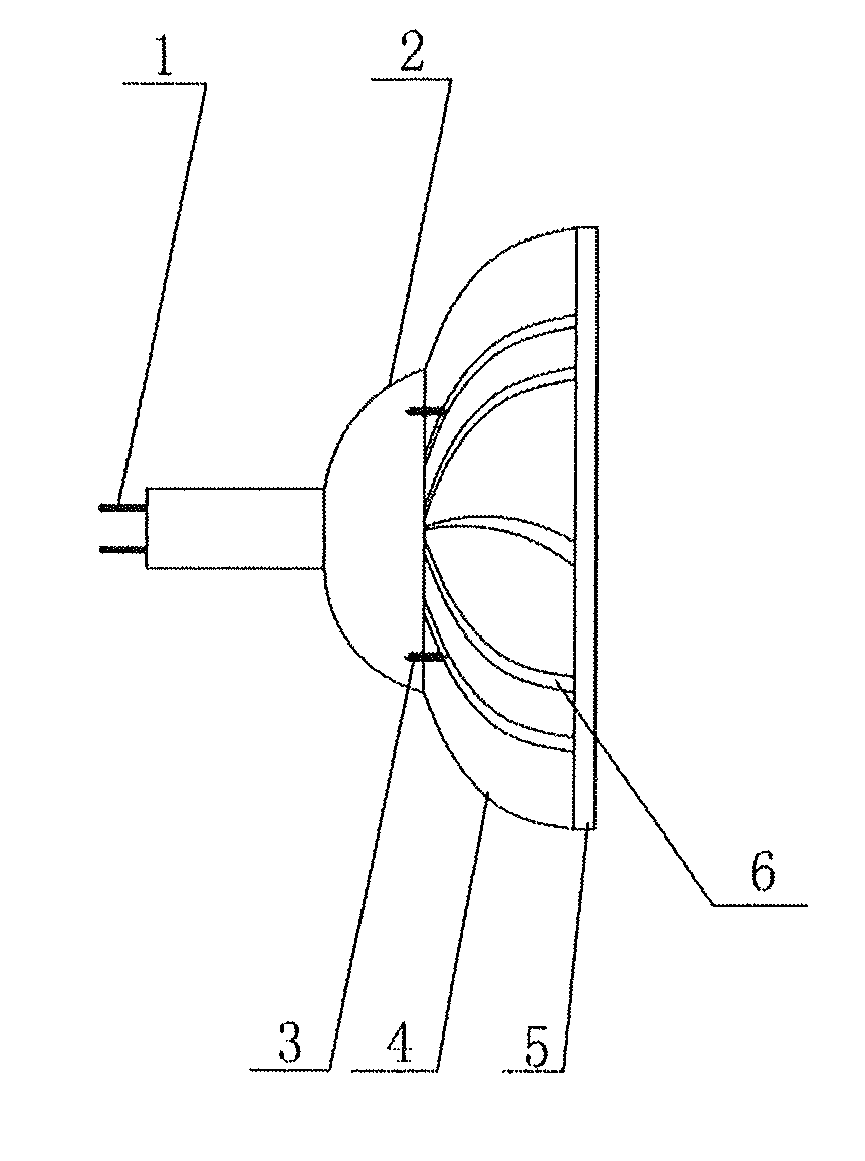
[0032]As shown in FIGS. 1 and 2, according to the present invention, the high-power LED lamp set includes: a power supply casing 2 and a light source casing 4 that are connected and fixed together via bolts 3, wherein the power supply casing 2 is used for housing a power converting module. The power supply casing 2 is made of plastic material and consisted of a rectangle part and a spherical part that are integrally formed as one-piece.

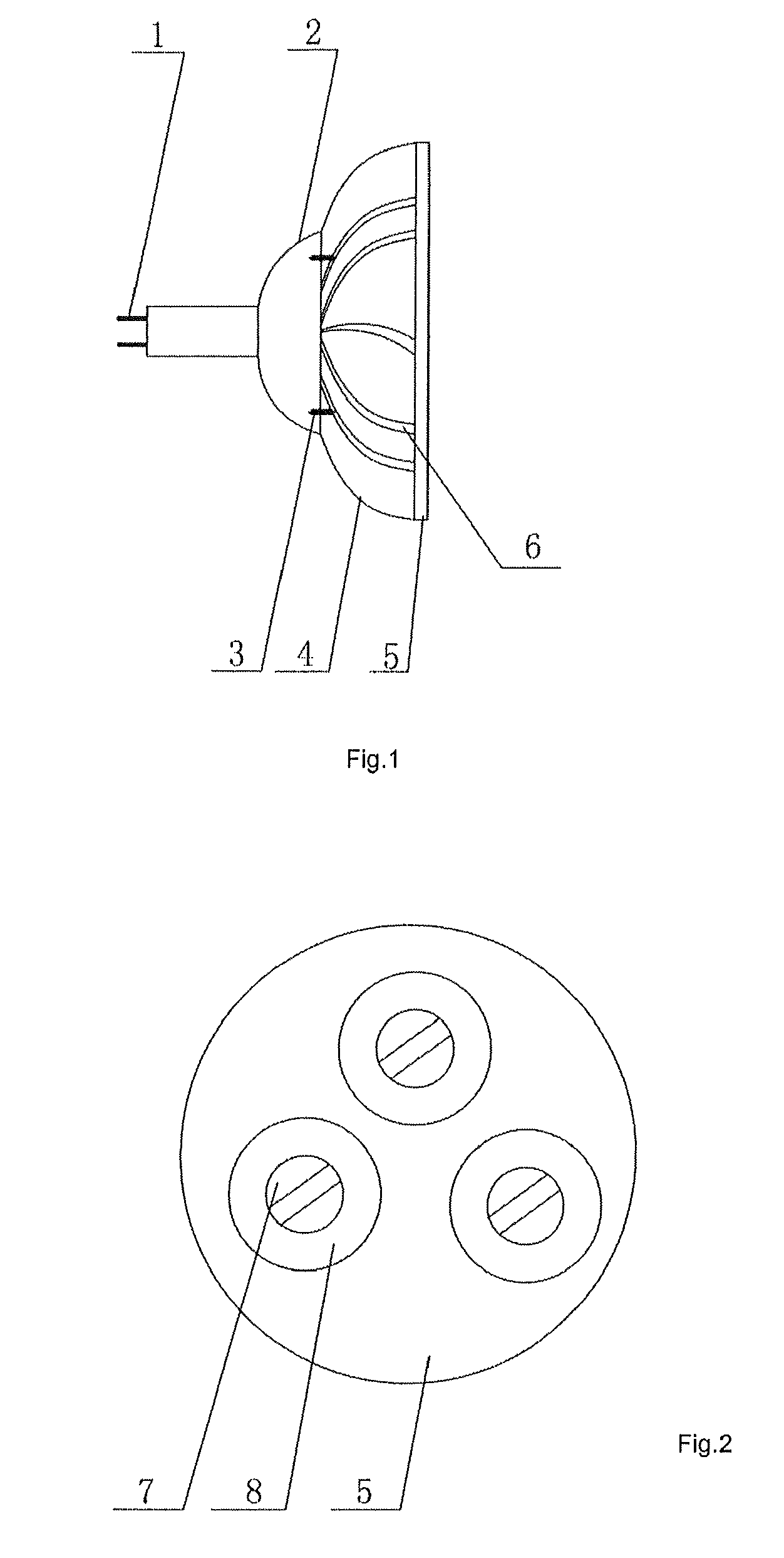
[0033]The light source casing 4 is made of aluminum alloy and has a bowl shape with a flat bottom. grooves 6 for heat dissipation are arranged on the external surface of the curving wall of the light source casing 4. Arranged on the bottom of the light source casing are 3-6 blind-holes, each having a small through-hole located at its center. Through each blind-hole and the respective small through-hole, one LED lamp 7 is mounted on the bottom surface of light source casing 4, and connected to the power converting module via a wire conductor passing th...


PUM


Abstract

A high-power LED lamp set is provided in the present invention. The high-power LED lamp set comprises: a power converting module; a power supply casing (2) for housing the power converting module; a light source casing (4), connected with the power supply casing; electrode rods (1), arranged at a rear end of the power supply casing (2) and connected with the power converting module; and LED lamps (7), mounted on a bottom surface of the light source casing (4); the light source casing (4) is provided with a lens board (5) at its opening end, wherein the lens board (5) is perforated with through holes at the positions corresponding to the LED lamps, and a high transmittance lens (8) is embedded in each of the through holes.

Description

CROSS-REFERENCE TO RELATED APPLICATIONS[0001]This application is a national stage application (under 35 U.S.C. §371) of PCT / CN2008 / 073020, filed Nov. 12, 2008, which claims priority from Chinese Application No. CN200720191684.3, filed Nov. 14, 2007.TECHNICAL FIELD[0002]The present invention relates to semiconductor lighting technology, and particularly to an integrated high-power LED lamp set.BACKGROUND[0003]LED is a kind of green and environment-friendly light source with the advantages of high luminous efficiency, less power consumption, long life, high reliability, easy to control, etc. LED is commonly used as a backlight source in mobile phones or as an indicator light in other devices, but its applications are not limited to this. LED also has promising prospect for its development and presents big market potential in the aspect of lighting application. Recently, LED has obtained so great development as to start its commercial application in lighting field and will gradually re...

Claims


Application Information

Patent Timeline
Patent Type & Authority Patents(United States)
IPC IPC(8): F21V21/00
CPCF21V23/026F21V29/004F21K9/137F21V29/89F21V5/04F21V23/023F21V29/80F21V5/007F21Y2101/02F21Y2105/001F21K9/233F21V29/507F21Y2105/10F21Y2115/10
Inventor LO, HONHUNGDING, KUAN
Owner LO HONHUNG
Why Eureka
Try Eureka