Supercharge Your Innovation With Domain-Expert AI Agents!

Electroluminescent display and driver circuit to reduce photoluminescence

A technology for photoluminescence and display drivers, applied in circuits, static indicators, electric solid-state devices, etc., can solve the problems of reducing photoluminescence, not applicable, not provided, etc.

Inactive Publication Date: 2013-04-03
CAMBRIDGE DISPLAY TECH LTD
View PDF20 Cites 8 Cited by
  • Summary
  • Abstract
  • Description
  • Claims
  • Application Information

AI Technical Summary

Problems solved by technology

However, this document does not attempt to reverse bias some pixels while forward biasing others, and is therefore not suitable for reducing photoluminescence stimulated by emission of pixels within a display.
Furthermore, this document does not provide any teaching on reverse biasing the display sufficiently to provide quenched photoluminescence to improve contrast.

Method used


Image

  • Electroluminescent display and driver circuit to reduce photoluminescence
  • Electroluminescent display and driver circuit to reduce photoluminescence
  • Electroluminescent display and driver circuit to reduce photoluminescence

Examples


Embodiment Construction

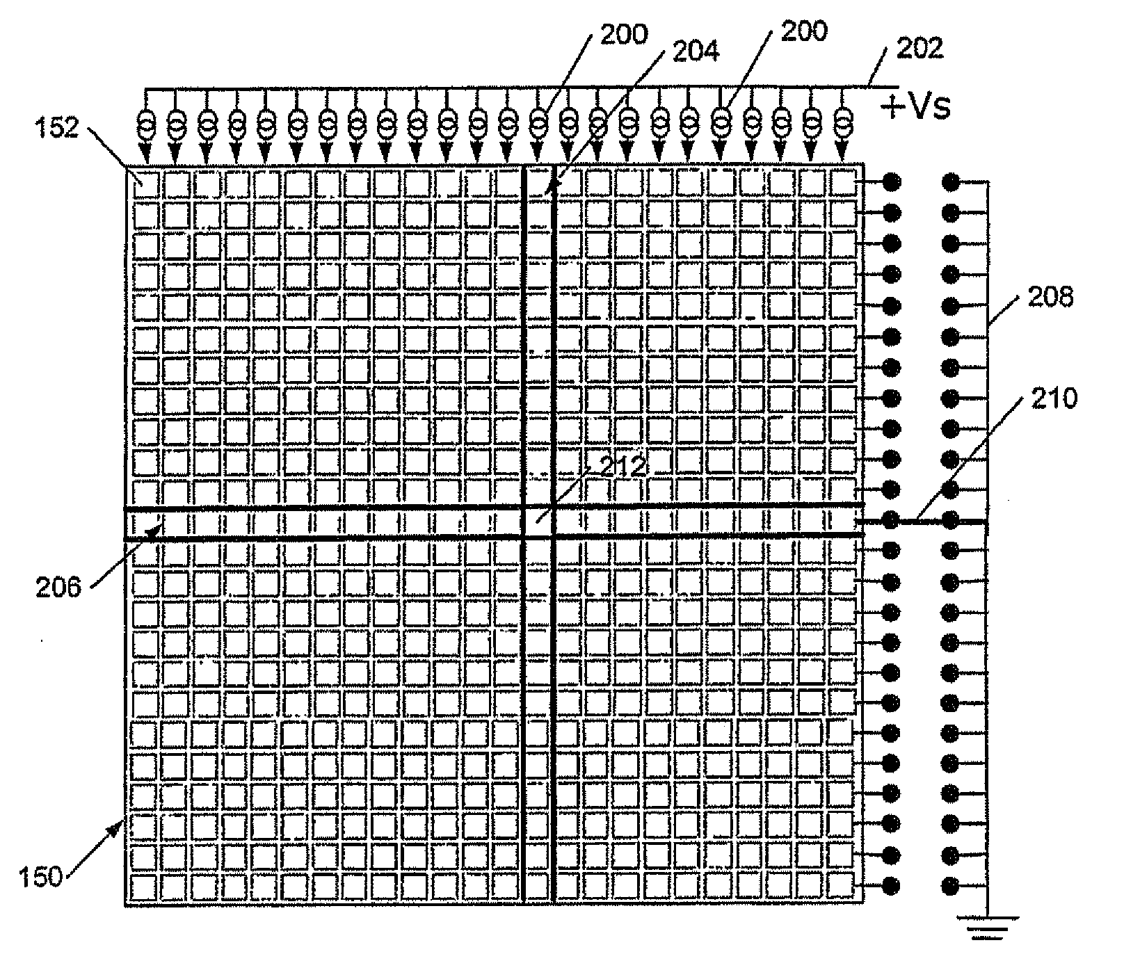
[0067] Applicants have realized that the contrast of light emitting diode based displays, eg passive or active matrix organic light emitting diode based displays, can be increased by reducing the contrast reducing photoluminescence. In the case of displays comprising light emitting diodes, especially organic light emitting diodes, this light can be reduced or quenched by reverse biasing a selected batch of light emitting diodes, i.e. those that are not emitting at any given moment Luminescence.

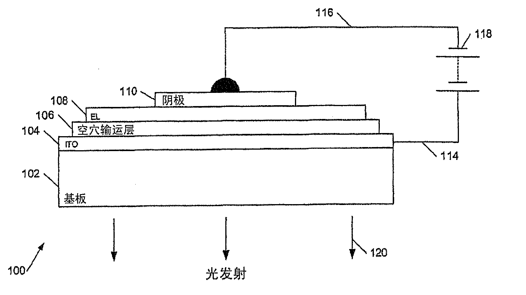
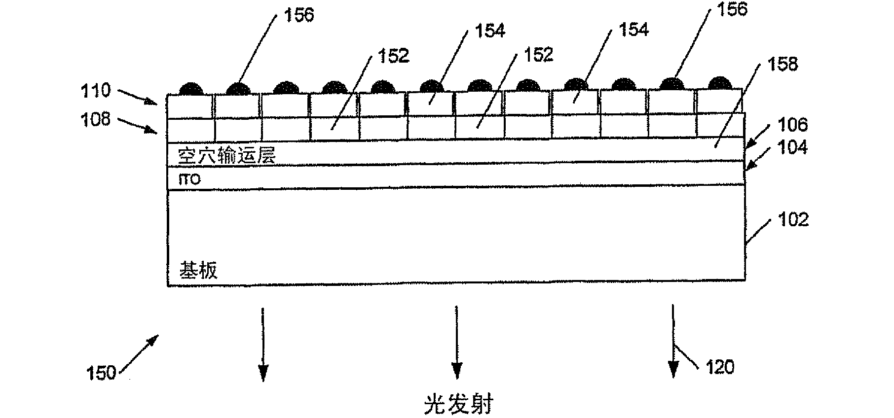
[0068] For example, consider a simple OLED display such as Figure 1a with 1b Display shown in , which is not forward biased or reverse biased. The apparent color of the (unlit) display is a combination of the color of the photoluminescence from the electroluminescent layer 108 of the display and the intrinsic color of said layer 108 and other modifying layers, especially the color of the cathode layer. Thus, for example, if the layer 108 is inherently colorless, and the photolumine...


PUM


Abstract

This invention generally relates to display driver circuits for electro-optic displays, and more particularly relates to circuits and methods for reducing the re-emission of absorbed light, for example to increase the colour gamut of organic light emitting diode displays. A driver for a display comprising a plurality of light emitting diode display elements, the driver comprising addressing circuitry to address said display elements, a first driver to cooperate with said address circuitry to provide a forward drive to at least one of said display elements to illuminate the display element, and a second driver to provide a reverse bias drive to others of said display elements at the same time as said at least one display element is illuminated to reduce a level of photoluminescence from said others of said display elements.

Description

technical field [0001] The present invention relates generally to display driver circuits for electro-optic displays, and more particularly to a circuit and method for reducing secondary emission of absorbed light, for example, to increase color shift in organic light emitting diode displays. Background technique [0002] Organic light emitting diodes (OLEDs) comprise a particularly advantageous form of electro-optic displays. They are bright, colorful, quickly switchable, and offer wide viewing angles, are easy to fabricate on a variety of substrates, and are inexpensive. Organic light-emitting diodes can be fabricated using polymers or small molecules in the color range (or in multicolor displays), depending on the materials used. Examples of polymer-based organic light-emitting diodes are described, for example, in WO 90 / 13148, WO 95 / 06400, WO 99 / 48160, while examples based on so-called small molecules are described in US Pat. No. 4,539,507. [0003] Figure 1a The basi...

Claims


Application Information

Patent Timeline
Patent Type & Authority Applications(China)
IPC IPC(8): G09G3/32H01L51/50G09G3/20G09G3/30G09G5/02H01L51/52
CPCG09G3/2014G09G3/2074G09G3/2077G09G3/3216G09G5/02G09G2310/0256G09G2320/0238G09G2320/0242G09G2320/0247G09G2320/043G09G2330/021H10K59/8791G09G3/30G09G3/20G09G3/32H10K50/86
Inventor 尤安·克里斯托弗·史密斯亚历克·戈尔丹·贡纳约纳松·詹姆斯·M·霍尔斯
Owner CAMBRIDGE DISPLAY TECH LTD
Features
  • R&D
  • Intellectual Property
  • Life Sciences
  • Materials
  • Tech Scout
  • Unparalleled Data Quality
  • Higher Quality Content
  • 60% Fewer Hallucinations
Learn More