X-ray lead room protecting device
A protection device, X-ray technology, applied in protected cells, nuclear engineering and other directions, can solve the problems of installation and maintenance difficulties, heat can not be dissipated, complex mechanical devices, etc., to achieve beautiful appearance, reduce reflection and leakage, reduce The effect of equipment weight
- Summary
- Abstract
- Description
- Claims
- Application Information
AI Technical Summary
Problems solved by technology
Method used
Image

Examples
Embodiment Construction
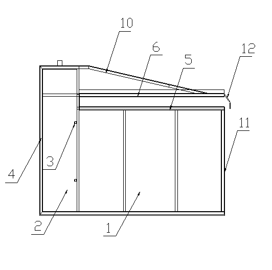
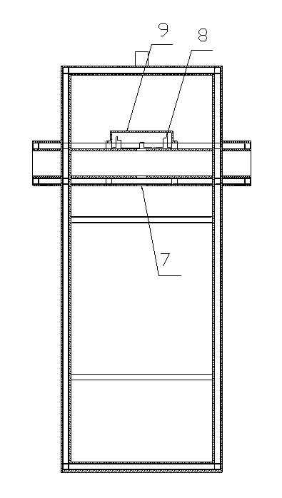
[0025] see figure 1 — figure 2 , the present invention relates to an X-ray lead room protection device, which includes a main box 1 and an electric control box 2, the main box 1 is used to install an X-ray control box and an X-ray emission source, and the electric control box The body 2 is installed on the back of the main box body 1, and the upper and lower parallel guide rails 3 are arranged on the board surface connected with the main box body 1 in the electric control box body 2, and the electric control rails 3 are arranged on the opposite side of the board surface. The control cabinet door 4 is provided with a lead guard plate I5 and a lead guard plate II6 parallel up and down on the top of the main box body 1, and the middle part of the lead guard plate I5 and the lead guard plate II6 is provided with a slit 7, so The slits 7 on the lead protective plate I5 and the lead protective plate II6 are aligned with each other, and a receiving plate 8 is arranged above the lea...
PUM
 Abstract
Description
Claims
Application Information
 - R&D
- Intellectual Property
- Life Sciences
- Materials
- Tech Scout
- Unparalleled Data Quality
- Higher Quality Content
- 60% Fewer Hallucinations
Browse by: Latest US Patents, China's latest patents, Technical Efficacy Thesaurus, Application Domain, Technology Topic, Popular Technical Reports.
© 2025 PatSnap. All rights reserved.Legal|Privacy policy|Modern Slavery Act Transparency Statement|Sitemap|About US| Contact US: help@patsnap.com