Power supplying device

A power supply device and fuel cell technology, which is applied to circuits, fuel cells, electrical components, etc., can solve problems such as inability to produce hydrogen, freezing of proton exchange membranes, damage, etc., and achieve the effect of improving power supply efficiency

Inactive Publication Date: 2013-04-03
YOUNG GREEN ENERGY
View PDF7 Cites 2 Cited by
  • Summary
  • Abstract
  • Description
  • Claims
  • Application Information

AI Technical Summary

Problems solved by technology

[0004] Since the fuel cell will produce water in the above reaction process, if the fuel cell is started or operated in a negative temperature environment (such as a low-temperature environment such as mountains and polar regions with a temperature below 0°C), water may be deposited on the surface of the proton exchange membrane. Icing occurs, causing the proton exchange membrane to be pierced by ice and damaged
In addition, if the reactant of fuel cell chemical hydrogen production is water, the water will freeze at negative temperature, resulting in the inability to react with other reactants for hydrogen production

Method used


Image

  • Power supplying device
  • Power supplying device
  • Power supplying device

Examples


Embodiment Construction

[0031] The aforementioned and other technical contents, features and effects of the present invention will be clearly presented in the following detailed descriptions of multiple embodiments with reference to the drawings. The directional terms mentioned in the following embodiments, such as "upper", "lower", "front", "rear", "left", "right", etc., are only referring to the directions of the attached drawings. Accordingly, the directional terms are used to illustrate, not to limit, the invention.

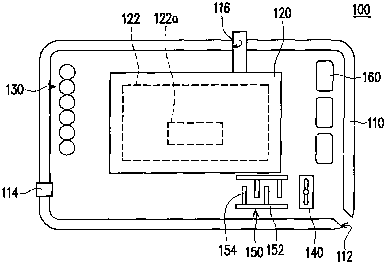
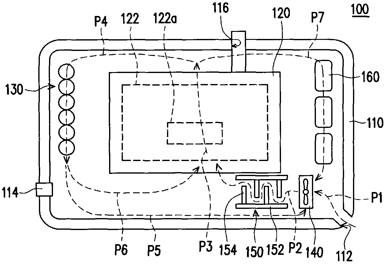
[0032] figure 1 It is a schematic diagram of a power supply device according to an embodiment of the present invention. figure 2 for figure 1 Schematic diagram of the gas flow within the power supply unit. Please refer to figure 1 and figure 2 , The power supply device 100 of this embodiment includes a first casing 110 , a second casing 120 , a battery module 130 , an air extraction element 140 and a heat exchange module 150 . The first casing 110 has an air hole 112 . The ...


PUM


Abstract

The invention relates to a power supplying device. The power supplying device comprises a first shell body, a second shell body, a cell module, an air pumping element and a heat exchange module, wherein the first shell body is provided with an air hole; the second shell body is arranged in the first shell body, and a fuel cell is arranged in the second shell body; the cell module is arranged in the first shell body, and the fuel cell and the cell module are used for supplying power to each other; the air pumping element is arranged in the first shell body, close to the air hole, and used for pumping gas into the first shell body through the air hole; and the heat exchange module is arranged in the first shell body and used for heating the gas, and at least part of the gas flows through the fuel cell and the cell module after the gas flows through the heat exchange module and is accordingly heated.

Description

【Technical field】 [0001] The present invention relates to a power supply device, and in particular to a power supply device using a fuel cell. 【Background technique】 [0002] Fuel Cell (FC) is a power generation device that converts chemical energy into electrical energy. Compared with traditional power generation methods, fuel cells have the advantages of low pollution, low noise, high energy density, and high energy conversion efficiency. , is a very future-looking clean energy, which can be applied in various fields such as portable electronic products, household power generation systems, transportation tools, military equipment, space industry, and small power generation systems. [0003] Various fuel cells have different application markets according to their operating principles and operating environments. The applications in mobile energy are mainly proton exchange membrane fuel cells (Proton Exchange Membrane fuel Cell, PEMFC) and direct methanol fuel cells ( Direct...

Claims


Application Information

Patent Timeline
Patent Type & Authority Applications(China)
IPC IPC(8): H01M8/04H01M8/00H01M8/06H01M8/10H01M8/12
CPCH01M8/04014H01M8/2475H01M2250/402H01M10/615H01M10/655H01M50/24Y02B90/10Y02E60/10Y02E60/50
Inventor 周柏圭杨建勋吴岳璋张文星林猷翔
Owner YOUNG GREEN ENERGY
Why Eureka
Try Eureka