Swirl self-priming pump

A self-priming pump and pump body technology, applied in the field of pump manufacturing, can solve the problems of increased manufacturing cost, short service life, and large environmental impact, and achieve the effects of reduced manufacturing cost, high work efficiency, and low scrap rate

Pending Publication Date: 2019-10-11
台州瑞亿机电有限公司
View PDF4 Cites 0 Cited by
  • Summary
  • Abstract
  • Description
  • Claims
  • Application Information

AI Technical Summary

Problems solved by technology

[0019] The upper mold and the lower mold of the pump casing are made of high-temperature alloy. The high-temperature alloy has the advantages of oxidation resistance, creep resistance and high strength. The upper and lower molds of the pump casing can be recycled, saving energy The consumption of the pump casing reduces the cost. The inner cavity mold of the pump casing is made of silicone rubber. The inner cavity mold of the pump casing is still elastic when heated to 150°C. When demoulding, the inner cavity mold of the pump casing is taken out from the inside of the pump casing to avoid scratches Damage the inside of the pump casing, but the life of the general silicone rubber mold is less than 20 molds, so the service life is short, and the silicone rubber mold needs to be continuously remanufactured, which increases the manufacturing cost and has many processes and a long molding cycle
[0020] There is also investment casting, that is, the outer surface of the mold tire made of plastic foam is rolled and coated, and after drying, it is placed in a sand box and the sand box is vacuumed before casting. The high-temperature molten iron burns the foam into gas and becomes This kind of casting of parts is also called vacuum casting, and the cost is high. The gas burned has a great impact on the environment.

Method used


Image

  • Swirl self-priming pump
  • Swirl self-priming pump
  • Swirl self-priming pump

Examples


Embodiment Construction

[0050] In order to further explain the technical means and effects of the present invention to achieve the intended purpose of the invention, the specific implementation, structure, features and effects of the present invention will be described in detail below in conjunction with the accompanying drawings and preferred embodiments.

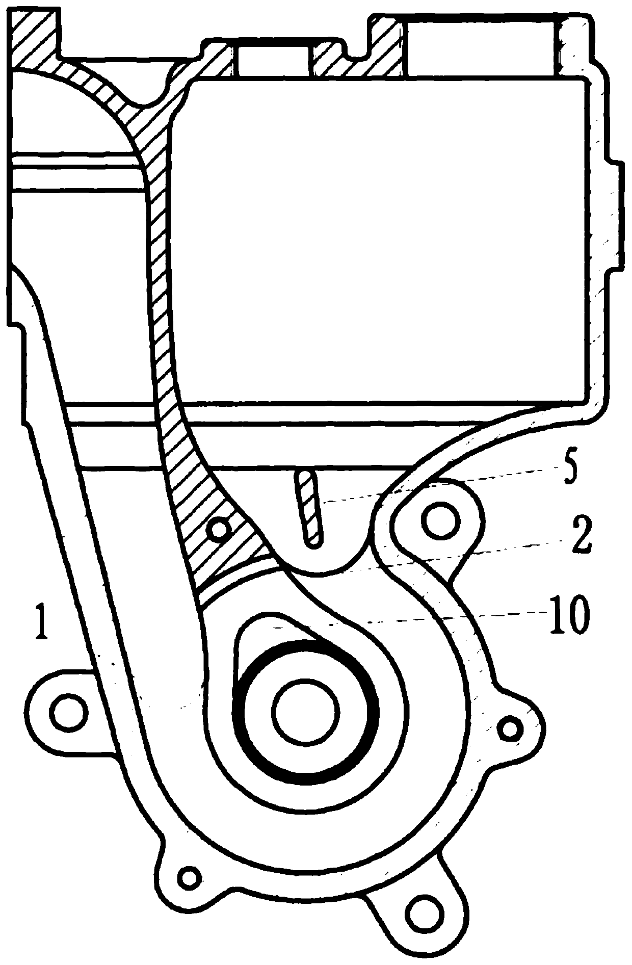
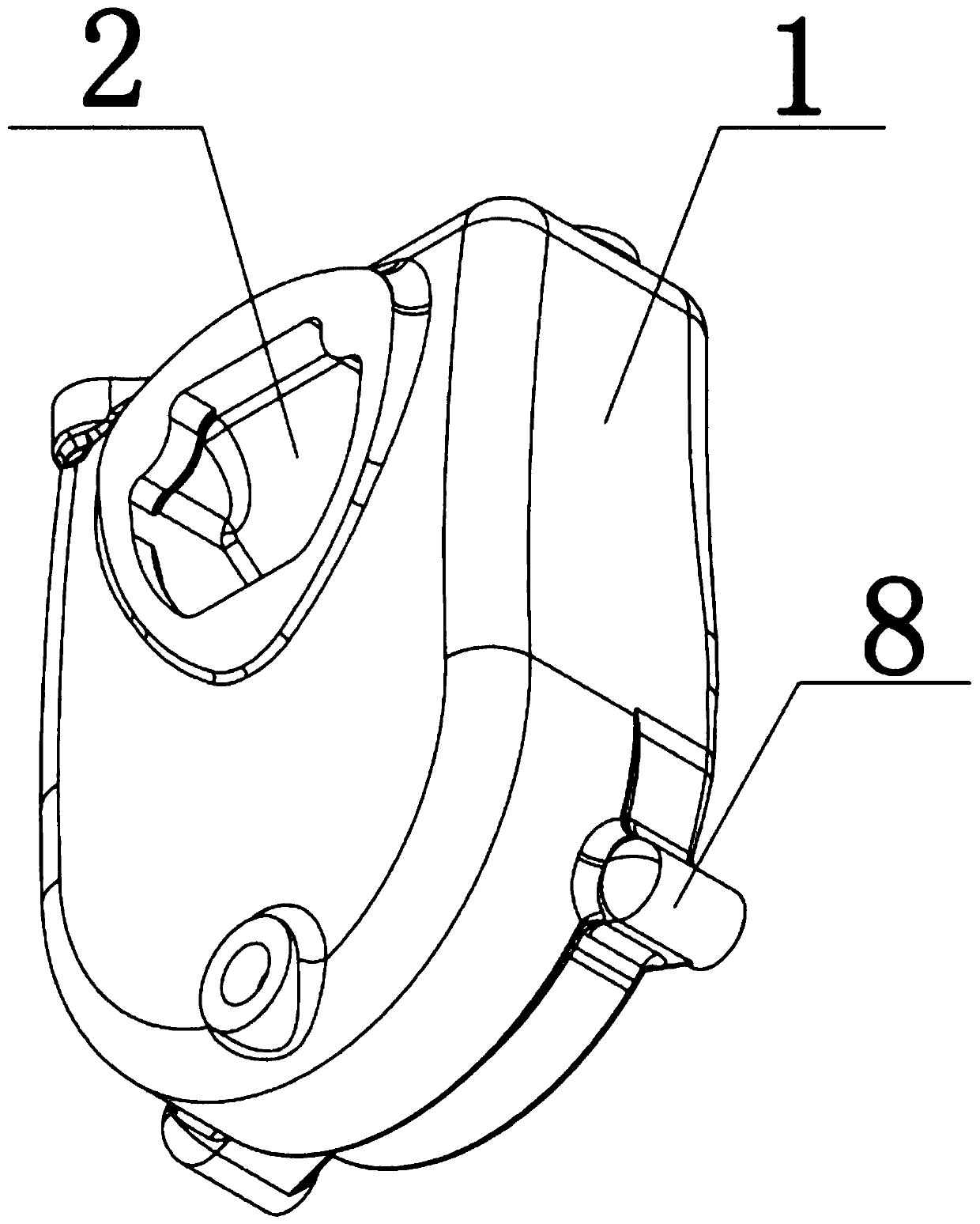
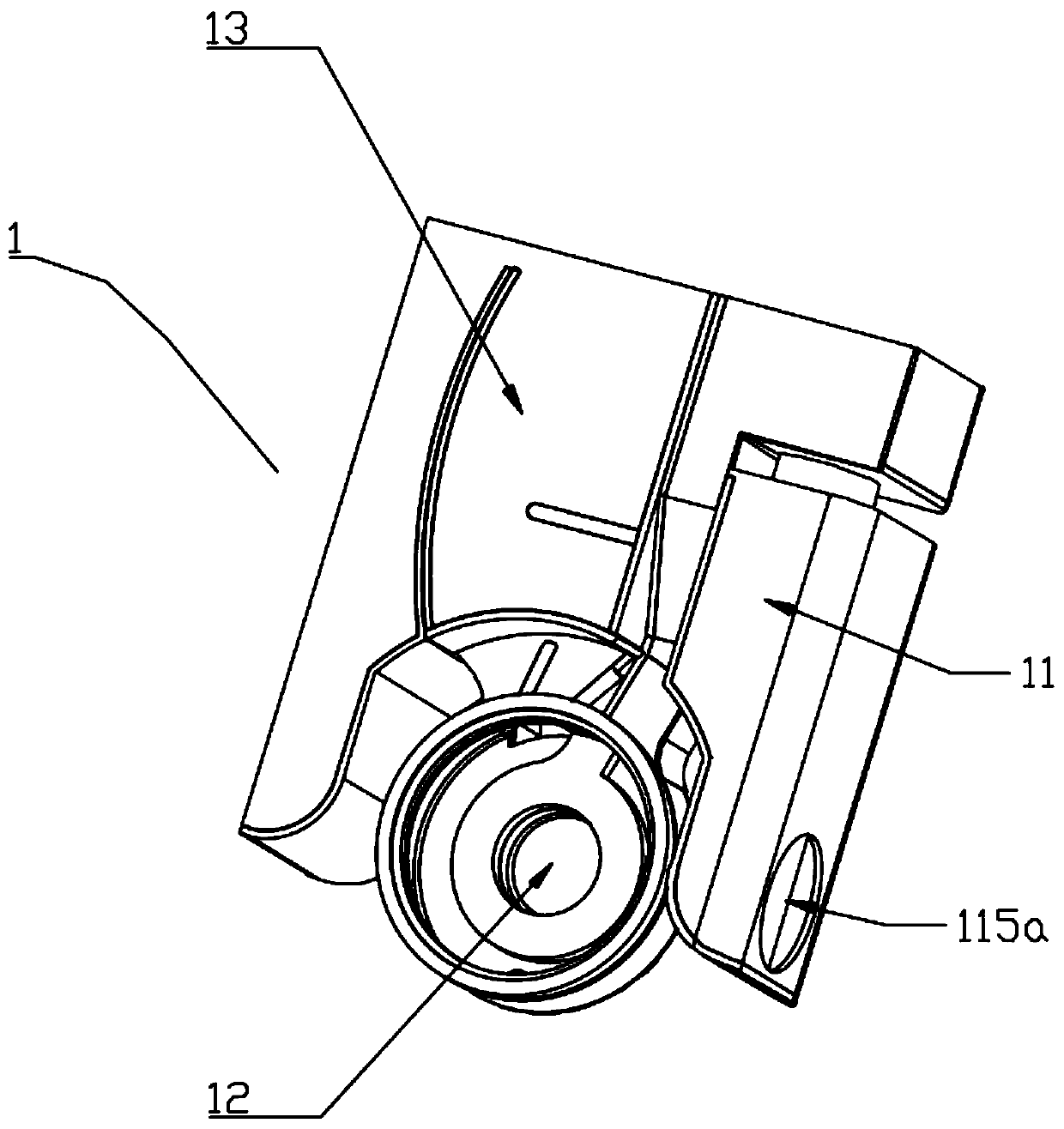
[0051] See image 3 , Figure 4 , The swirl self-priming pump of the first embodiment of the present invention, the swirl self-priming pump includes: a pump body 1 and a motor (not shown), the pump body 1 includes a suction chamber 11, an impeller chamber 12 and a discharge chamber 13.

[0052] See Figure 5 , Figure 6 , the suction chamber 11 includes: steel plate A, steel plate B, steel plate C, the first partition plate 111, the second partition plate 112 and the third partition plate 113 which are arranged in turn from right to left between the steel plate A, steel plate B and steel plate C The steel plate A and the first partition 111 co...


PUM


Abstract

The invention relates to the technical field of pump manufacturing, in particular to a swirl self-priming pump. The swirl self-priming pump comprises a motor and a pump body. The pump body comprises asuction chamber, an impeller chamber and an extrusion chamber, wherein the suction chamber, the impeller chamber and the extrusion chamber are provided with steel plates which are correspondingly machined and formed, and the steel plates are fixed through welding. According to the swirl self-priming pump, the pump body is formed by welding and fixing the steel plates corresponding to the suctionchamber, the impeller chamber and the extrusion chamber, the surface precision of the steel plates is high, so that water flow can smoothly enter each channel, the volume loss is reduced, the hydraulic efficiency is improved, the problem that shrinkage holes are likely to be formed in the cooling and solidification time after casting is solved, normal operation of the swirl self-priming pump is prevented from being affected, and working efficiency is high.

Description

technical field [0001] The invention relates to the technical field of pump manufacture, in particular to a swirl self-priming pump. Background technique [0002] The flow channel of the pump body in the existing self-priming pump on the market is too narrow because the flow channel area is too small, and the outlet of the flow channel is provided with a corner, and the cross-sectional area of ​​the flow channel varies unevenly, resulting in low hydraulic efficiency during the working process, thus wasting Some unnecessary hydraulic resources, due to the unreasonable structure of the stator and rotor in the motor, the distribution of the magnetic flux density and magnetic circuit in each part of the motor core is unbalanced, resulting in a large loss, and the increase in harmonics causes a series of adverse effects, resulting in self-priming The overall efficiency of the pump is not high, wasting unnecessary hydraulic and electrical resources. [0003] See figure 1 , the C...

Claims


Application Information

Patent Timeline
Patent Type & Authority Applications(China)
IPC IPC(8): F04D9/02F04D13/06F04D15/02F04D29/42
CPCF04D9/02F04D13/06F04D15/0218F04D29/4266
Inventor 戴荷生潘林福宗卫军潘柯越陈辉
Owner 台州瑞亿机电有限公司
Why Eureka
Try Eureka