Antenna, antenna unit thereof and wireless communication device equipped with antenna

An antenna unit and antenna technology, which is applied to antenna grounding devices, antennas, antenna arrays, etc., can solve the problems of damaging GPS receiving chips, adding electrostatic protection devices, and unsatisfactory effects, so as to improve efficiency, good antenna performance, and prevent static electricity The effect of breakdown

Inactive Publication Date: 2013-04-03
珠海德百祺科技有限公司
View PDF3 Cites 9 Cited by
  • Summary
  • Abstract
  • Description
  • Claims
  • Application Information

AI Technical Summary

Problems solved by technology

The disadvantage of this antenna is that when the static electricity is discharged, the discharge current flows along the antenna to the GPS receiving chip, which may damage the GPS receiving chip
Although some electrostatic protection devices can be added, the effect is not ideal
At the same time, adding electrostatic protection devices will greatly increase the manufacturing cost of mobile terminals

Method used


Image

  • Antenna, antenna unit thereof and wireless communication device equipped with antenna
  • Antenna, antenna unit thereof and wireless communication device equipped with antenna
  • Antenna, antenna unit thereof and wireless communication device equipped with antenna

Examples


Embodiment 1

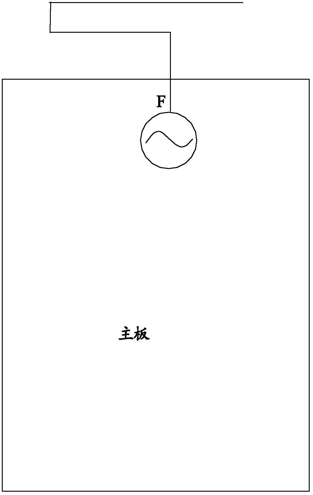
[0042] Such as figure 2 Shown is a schematic diagram of the antenna of Embodiment 1 of the present invention.

[0043] In this embodiment, the antenna unit includes a first antenna element and a second antenna element.

[0044] The first antenna component includes a first part F1 and a second part F2, wherein the first end of the first part F1 (corresponding to the lower end in the figure) is a feed point and the feed point is the same as the feed point on the main board 100 (F ) are electrically connected, and one end of the second part F2 is electrically connected with the second end (corresponding to the upper end in the figure) of the first part F1 to form a L monopole antenna. It should be noted here that although the first portion F1 and the second portion F2 shown in the figure are perpendicular to each other, in other embodiments of the present invention, the first portion F1 and the second portion F2 are not perpendicular to each other.

[0045] The second antenna ...

Embodiment 2

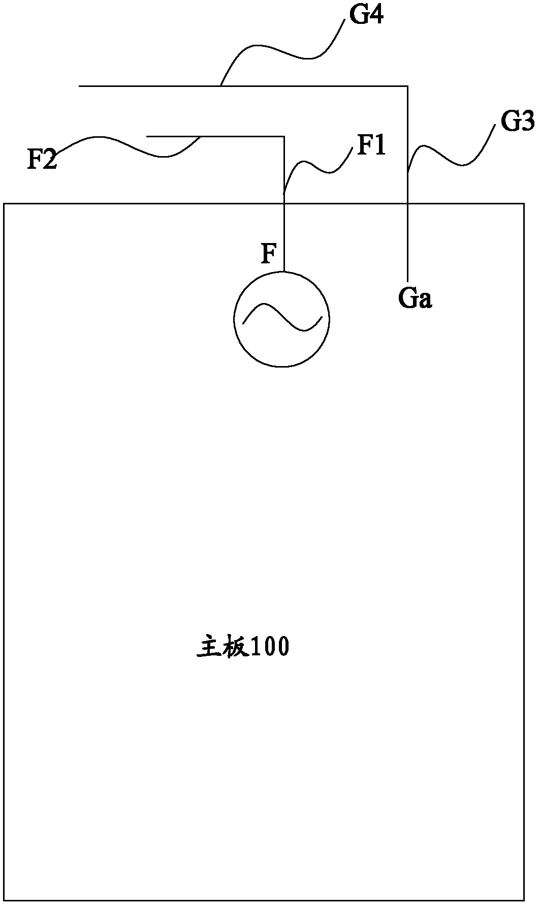
[0048] image 3 A schematic diagram of the antenna according to Embodiment 2 of the present invention is shown.

[0049] In this embodiment, the difference from Embodiment 1 is that the first antenna component is a T-shaped antenna component and the second antenna component includes two ground points.

[0050] Specifically, the first end of the first portion F1 is electrically connected to the second portion F2, thereby forming a T-shaped antenna component. It should also be noted that although the first end of the first part F1 is connected to the center of the second part F2 in the figure, the first end of the first part F1 can be connected to the center of the second part F2 in other embodiments of the present invention. connected anywhere.

[0051] The second antenna component includes a third part G3 and a fourth part G4 , the first end of the third part G3 is a ground point, and the ground point is electrically connected to the ground point (Ga) on the main board 100 ....

Embodiment 3

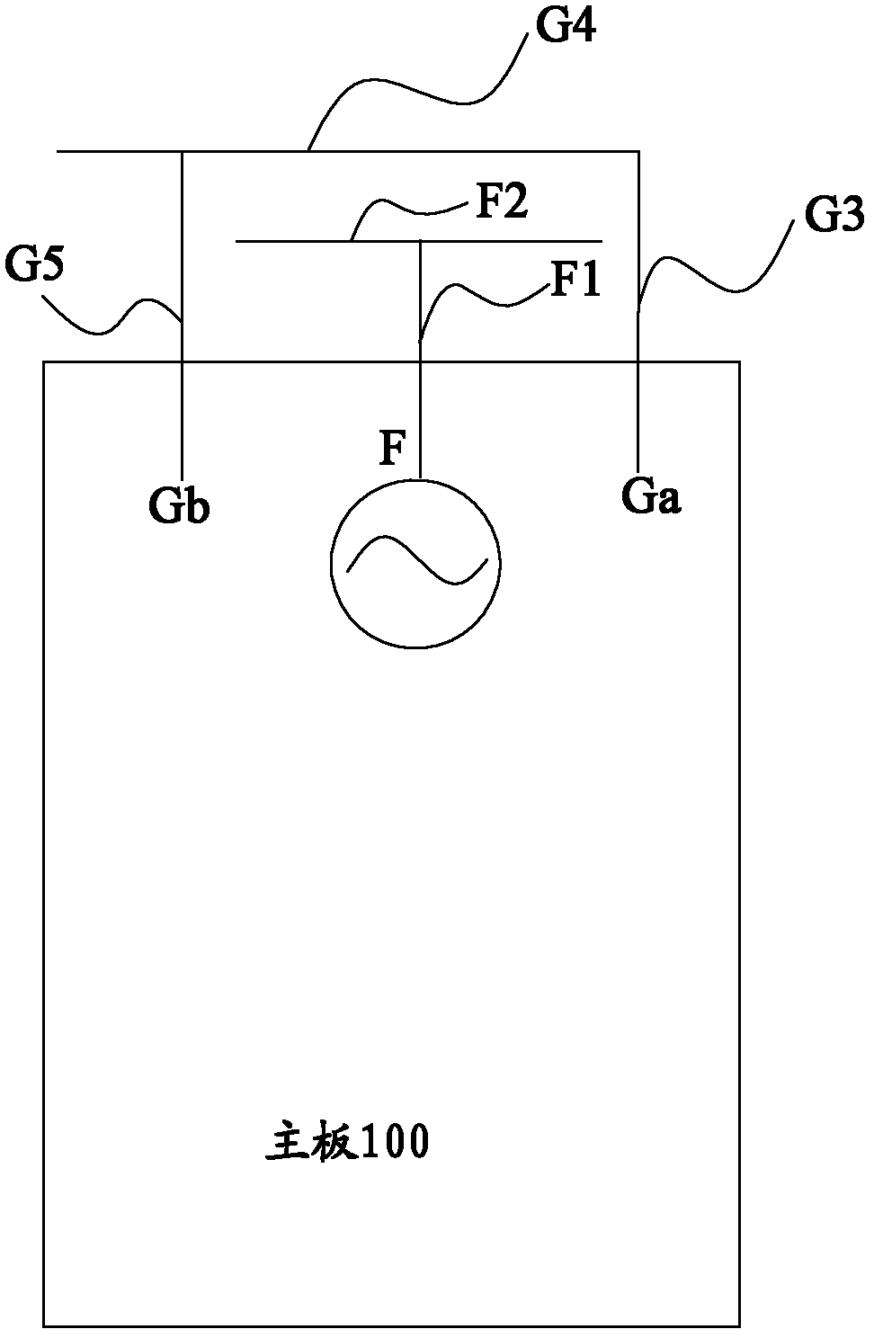
[0054] Such as Figure 4 Shown is a schematic diagram of the antenna according to Embodiment 3 of the present invention.

[0055] In this embodiment, the structure of the first antenna part is the same as the structure of the first antenna part in Embodiment 2. Different from Embodiment 2, in this embodiment, in order to improve the performance of the second antenna component, the second antenna component also includes a seventh part G7 in addition to the third part G3, the fourth part G4 and the fifth part G5 and the eighth part G8, wherein the seventh part G7 is coupled to the fourth part G4, and the seventh part G7 is electrically connected to the fourth part G4 through the eighth part G8 so as to improve the overall antenna efficiency.


PUM


Abstract

The invention provides an antenna, an antenna unit thereof and a wireless communication device equipped with the antenna. The antenna unit comprises a first antenna part which comprises a feeding point and a second feeding point part which comprises at least one earth point, wherein the first antenna part and the second antenna part are mutually separated; the second antenna part at least partially surrounds the first antenna part and a part of the first antenna part is intercoupled with a part of the second antenna part to form a first coupling capacitor. The antenna unit provided by the embodiment of the invention leads current of electrostatic discharge to firstly arrive at the second antenna part without arriving at the first antenna part and affecting the chip on the mainboard which is connected with the feeding point of the first antenna part. Besides, the antenna unit provided by the embodiment of the invention not only realizes the radiating function of the antenna together with the mainboard, but also can effectively improve the efficiency of the antenna.

Description

technical field [0001] The present invention relates to the field of communication technology, in particular to an antenna, its antenna unit and a wireless communication device with the antenna. Background technique [0002] Antennas such as GPS, Bluetooth, and WiFi on mobile terminals are composed of a PCB main board and an antenna unit, wherein the PCB main board constitutes one unit of the antenna, and the antenna unit constitutes another unit of the antenna. Usually, these antenna units have a feed point, and the antenna unit is electrically connected to the transceiver circuit of the PCB main board through the feed point. [0003] The reliability test of the mobile terminal includes an electrostatic discharge test. The Chinese standard requires that it can withstand an electrostatic discharge of 8KV without any specified failure. A common anti-static measure is to add an electrostatic protection device on the PCB. However, the antistatic device is not particularly effe...

Claims


Application Information

Patent Timeline
Patent Type & Authority Applications(China)
IPC IPC(8): H01Q1/36H01Q1/48H01Q21/00H04B1/38H04B1/40
Inventor 漆一宏
Owner 珠海德百祺科技有限公司
Why Eureka
Try Eureka