Digital automatic gain control method and device of receiver

An automatic gain control and receiver technology, applied in the field of communication, can solve problems such as complex calculation methods, data polarization, and low efficiency, and achieve the effects of simple calculation methods, improved efficiency, and reduced differences

Active Publication Date: 2013-04-03
COMBA TELECOM SYST CHINA LTD
View PDF3 Cites 5 Cited by
  • Summary
  • Abstract
  • Description
  • Claims
  • Application Information

AI Technical Summary

Problems solved by technology

The traditional DAGC determines how to shift according to the signal-to-noise ratio or power, etc. The calculation method is complex and inefficient, and the same shifting method is used for all user data, resulting in serious polarization of the output data, namely The data with a larger value becomes larger, and the data with a smaller value becomes smaller

Method used


Image

  • Digital automatic gain control method and device of receiver
  • Digital automatic gain control method and device of receiver
  • Digital automatic gain control method and device of receiver

Examples


Embodiment 1

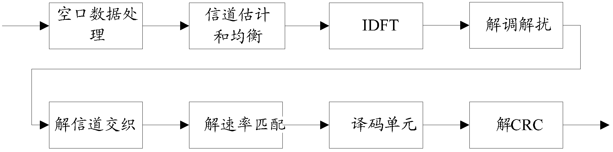
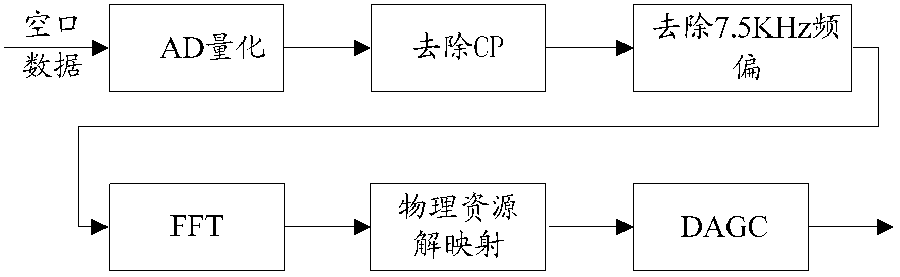
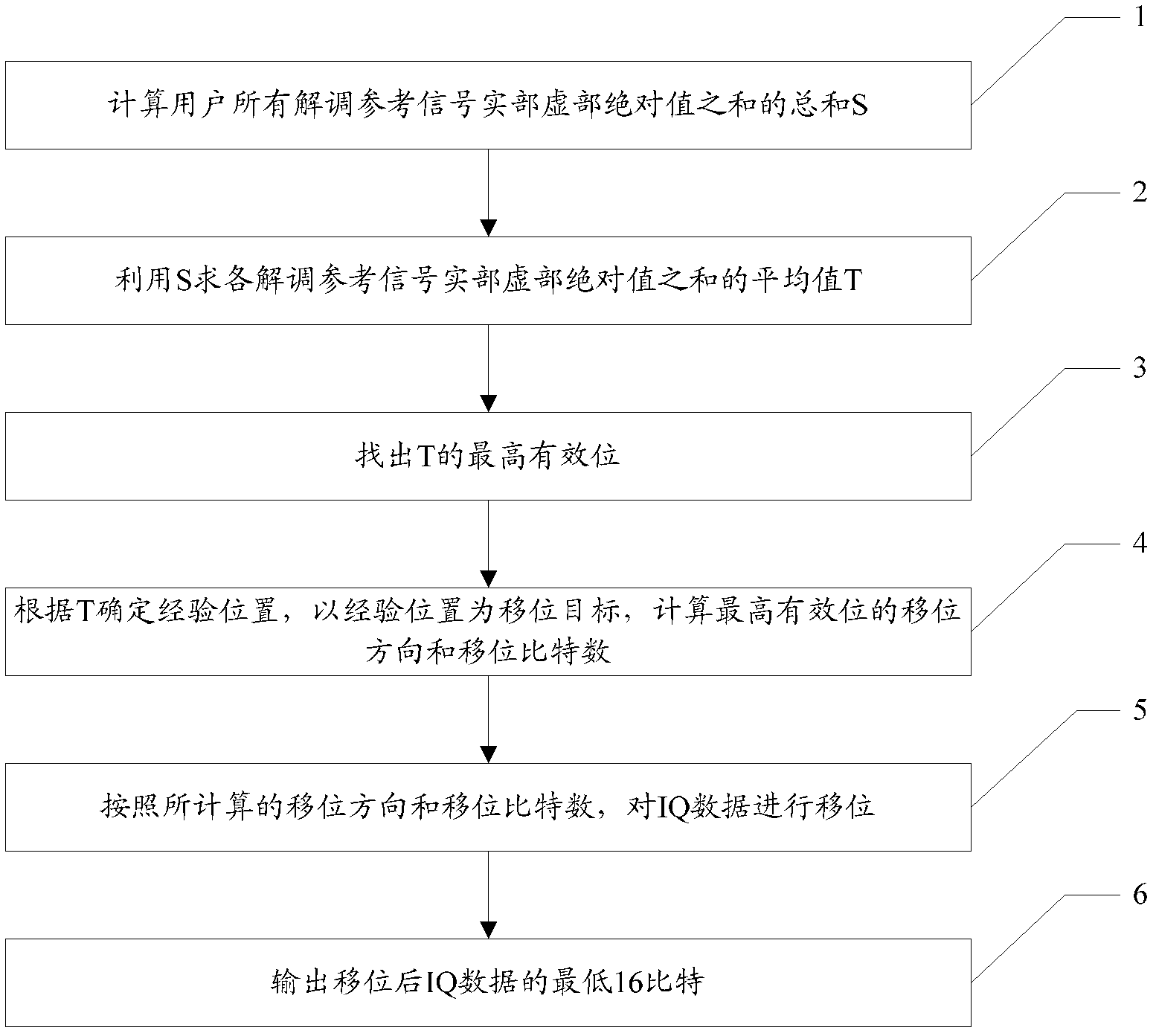
[0047] In this embodiment, the LTE uplink receiver is described as follows. The user air interface data is sequentially processed by AD quantization, cyclic prefix CP removal, 7.5KHz frequency offset removal, FFT and physical resource demapping, and becomes IQ data in the frequency domain. I is the same Phase (In-phase) component; Q is a 90-degree quadrature (Quadrate) component; IQ is quadrature. Such as image 3 As shown, in this embodiment, the following steps are respectively performed for the IQ data in the frequency domain of each user:

[0048] Step 1. Determine the demodulation reference signal (r dmrs,j ) of the I way (real part) and the sum S of the absolute value sum of the Q way (imaginary part), the calculation formula of S can be:

[0049] S = Σ j = 0 12 * n - 1 ...

Embodiment 2

[0059] In order to improve the data accuracy, the present embodiment further limits the FFT. After its processing, the output is 32-bit full-precision IQ data, and then steps 1-6 process all 32-bit IQ data. Before the step 6 output , IQ data may overflow, therefore, this embodiment increases the judgment and processing of overflow.

[0060] Such as Figure 4 As shown, step 7 is also included after step 5:

[0061] Judging whether the shifted IQ data overflows, if not, step 6 outputs the lowest 16 bits of the IQ data, and if overflows, performs a clipping operation on the IQ data. Whether overflow is judged based on whether the number of effective bits of the shifted IQ data is greater than 15 (the effective data length is up to 15 bits, and the highest bit is the sign bit, which is not included in the effective data length). If it is less than or equal to 15, it does not overflow, and directly Proceed to step 6; if it is greater than 15, it overflows, and if the data overflo...

Embodiment 3

[0064] The LTE receiver includes more than one antenna, and the hardware configuration of each antenna is different, and the corresponding demodulation reference signal is also different. Considering this situation, this embodiment improves step 1. The S is calculated for each antenna, and then the average value of S corresponding to all antennas is calculated, and the average value is used as the final S, so that the obtained S is more representative.

[0065] In addition, you can also use the inline instruction _norm in the fixed-point DSP to complete step 3.

[0066] Other technical features of this embodiment are the same as those of Embodiment 2, and will not be repeated here.

[0067] The digital automatic gain control device for the LTE uplink receiver according to the embodiment of the present invention is a device corresponding to the digital automatic gain control method for the LTE uplink receiver according to the embodiment of the present invention. The device wil...


PUM


Abstract

The embodiment of the invention discloses a digital automatic gain control method of a receiver, and the method is used for respectively controlling each user. The digital automatic gain control method comprises the following steps of: firstly, calculating an average value of a sum of absolute values of a real part and an imaginary part of user demodulation reference signals; selecting an experience position according to the size of the average value; determining a shift direction and a shift bit according to a direction of the most significant bit of the average value related to the experience position and a bit distance; carrying out shift treatment on IQ (Intelligence Quotient) data of the user according to the determined shift direction and shift bit; and carrying out amplitude limiting operation and outputting the IQ data over-flown after shifting. An operational method related by a process for determining how to shift only comprises addition and subtraction operation with finite iteration, shift and primary division operation, so that the calculation is simple; and furthermore, the data of each user is respectively suitably treated, so that the difference of the data among the different users can be reduced. The embodiment of the invention further discloses a device corresponding to the method. The method and the device are used in a combined manner, so that the digital automatic gain control can be realized.

Description

technical field [0001] The invention relates to the technical field of communication, in particular to a receiver digital automatic gain control method and device. Background technique [0002] Such as figure 1 Shown is a schematic diagram of the internal structure of the LTE uplink receiver, figure 2 Shown is a schematic diagram of the internal structure of the air interface data processing module. After the air interface data is quantized after analog-to-digital conversion (AD quantization), the cyclic prefix CP is removed, the 7.5KHz frequency offset is removed, FFT and physical resource demapping are processed, it becomes The 16-bit IQ data is output after the shift operation of the last link digital automatic gain control (DAGC). The process of digital automatic gain control is the process of shifting, and the process of determining how to shift is the key to measure the digital automatic gain control method. The traditional DAGC determines how to shift according to...

Claims


Application Information

Patent Timeline
Patent Type & Authority Applications(China)
IPC IPC(8): H04W52/52
Inventor 阮俊冰区洋
Owner COMBA TELECOM SYST CHINA LTD
Why Eureka
Try Eureka