
Egr construction for opposed-piston engines

A piston engine, opposed technology, applied to reciprocating piston engines, variable displacement engines, engine components, etc., can solve problems such as pressure difference

Active Publication Date: 2013-04-03
ACHATES POWERS INC
View PDF9 Cites 15 Cited by
  • Summary
  • Abstract
  • Description
  • Claims
  • Application Information

AI Technical Summary

Problems solved by technology

However, this EGR configuration is not directly applicable in a two-stroke opposed-piston engine with direct-flow scavenging because of the pressure differential that needs to be created in an opposed-piston engine to pump the exhaust into the inflow of air

Method used


Image

  • Egr construction for opposed-piston engines
  • Egr construction for opposed-piston engines
  • Egr construction for opposed-piston engines

Examples


Embodiment Construction

[0016] The EGR structure described in this specification occurs in the illustrative context comprising a ported, 1st line scavenged opposed-piston engine having at least one cylinder in which a pair of pistons are disposed with their end surfaces facing each other. A "ported" cylinder includes one or more intake and exhaust ports machined or formed in its side walls. This illustrative context is intended, by way of illustration, to provide a basis for understanding embodiments of various EGR structures.

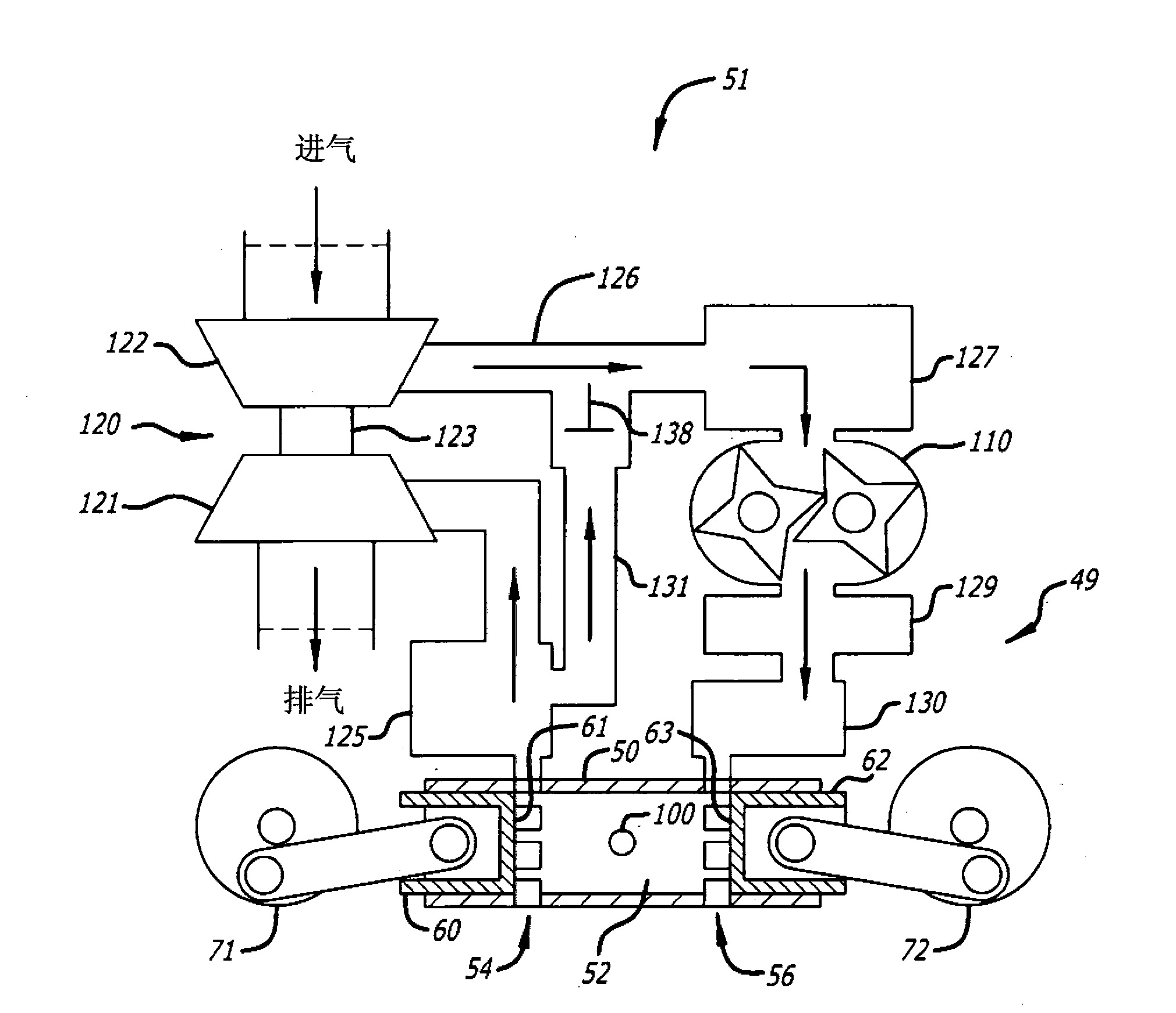
[0017] exist image 3 In the embodiment, the internal combustion engine 49 is embodied by an opposed piston engine having at least one ported cylinder 50 . For example, the engine may have one ported cylinder, two ported cylinders, three ported cylinders, or four or more ported cylinders. For the sake of illustration, in these illustrated and described examples, the engine is an opposed piston engine assumed to have multiple ported cylinders. In this regard, each cylinder 5...


PUM


Abstract

A two-stroke, opposed-piston engine (49) with one or more ported cylinders (c) and uniflow scavenging includes an exhaust gas recirculation (EGR) construction (131) that provides a portion of the exhaust gasses produced by the engine (49) for mixture with charge air to control the production of NOx during combustion.

Description

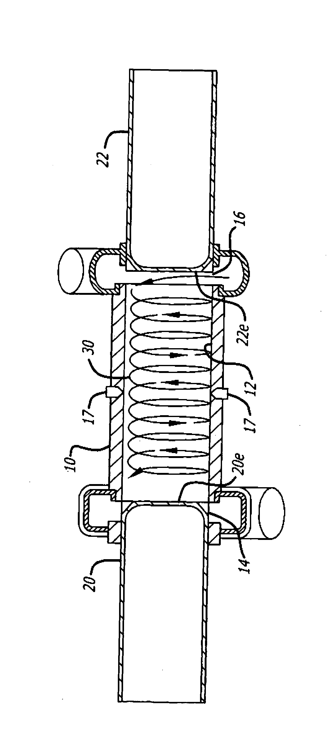
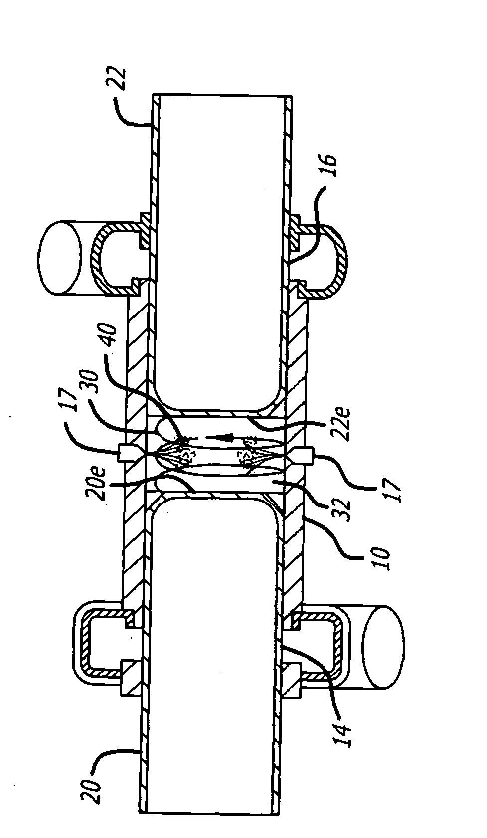
Background technique [0001] The field is internal combustion engines. In particular, the field relates to ported direct-flow scavenged opposed-piston engines with exhaust gas recirculation. More specifically, the field includes two-stroke opposed-piston engines having one or more ported cylinders and direct-flow scavenging, wherein exhaust gas recirculation (EGR) configurations provide a portion of the exhaust gas generated by the engine. Gas is used to mix with charge air to control NOx production during combustion. [0002] As seen in Figure 1, the internal combustion engine is shown with an opposed piston engine comprising ports 12 machined or formed therein and longitudinally disposed / displaced exhaust ports and intake ports 14 and 16 of at least one cylinder 10 . The fuel injection nozzle 17 is at or near the longitudinal center of the cylinder, and is arranged in or adjacent to the nozzle hole opening through the side of the cylinder. Two pistons 20, 22 are arranged ...

Claims


Application Information

Patent Timeline
Patent Type & Authority Applications(China)
IPC IPC(8): F02B25/08F02B29/04F02B37/013F02B75/28F02M25/07F02B37/16F02B37/18
CPCF01B7/02F02B25/08F02B75/28F02B23/0645F02B2275/14F02F1/186F02B2075/025
Inventor E·P·迪昂I·J·L·瑞迪F·G·勒东G·雷格纳M·H·瓦尔
Owner ACHATES POWERS INC
Learn More