Phosphor-coated light-emitting device

A technology for light-emitting devices and phosphors, applied in the directions of light-emitting materials, lighting devices, electroluminescent light sources, etc., can solve the problems of accelerated temperature degradation and insufficient cooling of the phosphor part, and achieve simple structure, high brightness, small size, etc. The effect of etendue

Active Publication Date: 2013-04-03
NEC CORP
View PDF7 Cites 3 Cited by
  • Summary
  • Abstract
  • Description
  • Claims
  • Application Information

AI Technical Summary

Problems solved by technology

However, the phosphor portion near the upper surface of the phosphor 603 irradiated by the excitation laser beam 604 is not sufficiently cooled.
As a result, an increase in temperature accelerates the deterioration of

Method used


Image

  • Phosphor-coated light-emitting device
  • Phosphor-coated light-emitting device
  • Phosphor-coated light-emitting device

Examples


Embodiment Construction

[0036] Hereinafter, embodiments of the present invention will be described with reference to the drawings.

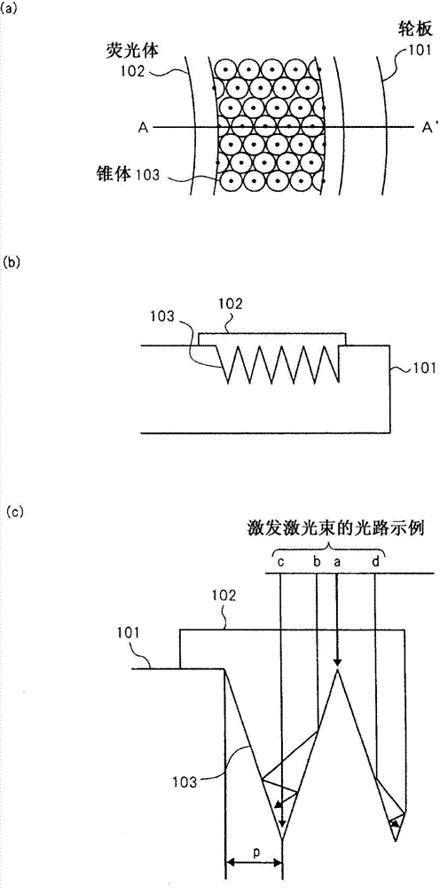
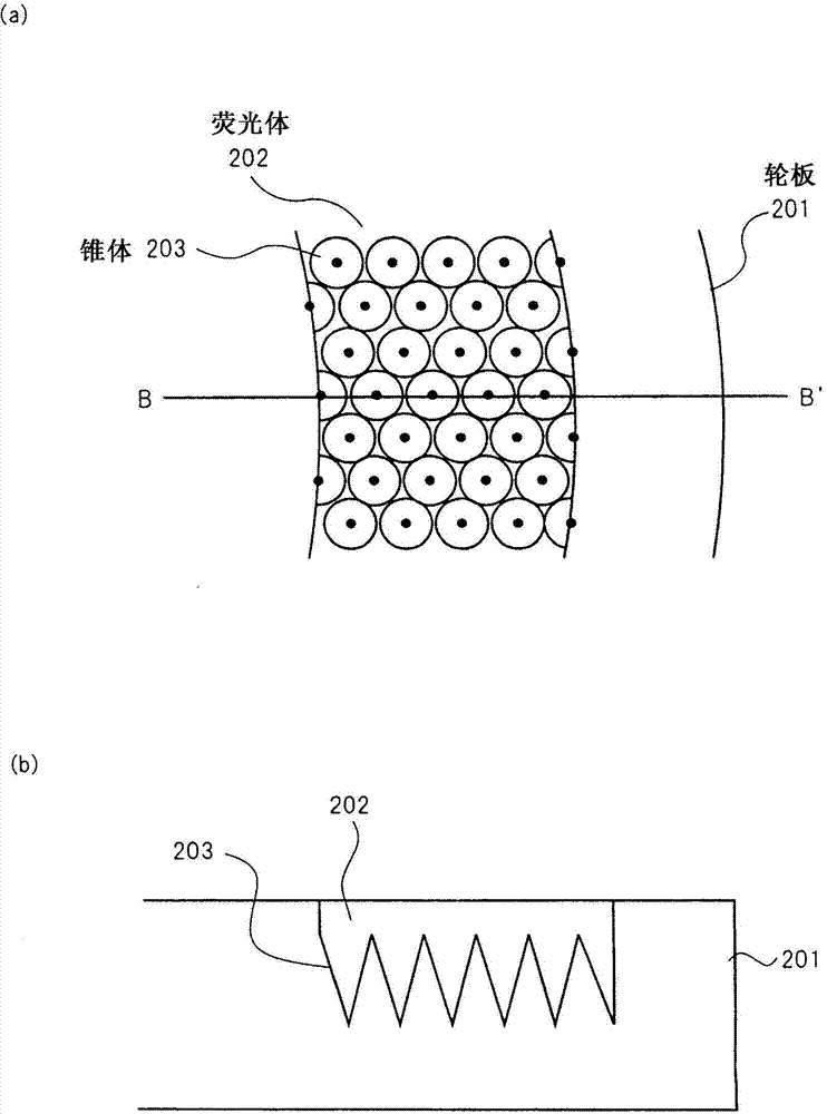
[0037] figure 2 A to 2C are main component views of the phosphor-coated light emitting device according to the first embodiment of the present invention. figure 2 A is a partial plan; figure 2 B is along figure 2 A cross-sectional view taken along line A-A' in A; and figure 2 C is figure 2 Partial enlarged view of B.

[0038] In this example, as in figure 1 In the case of the light-emitting devices shown in A to 1C, the phosphor 102 is formed in a circle shape on a circular flat wheel plate 101 that rotates around an axis. In the position of the wheel plate 101 where the phosphor 102 is formed, a plurality of conical protrusions 103 are formed with the upper surface side of the wheel plate 101 as the apex, and the phosphor 102 enters between the cones 103 .

[0039] The excitation laser beam enters the phosphor 102 from the upper part of the phosphor 102 . ...


PUM


Abstract

The present invention provides a phosphor-coated light-emitting device which has a simple structure and enables the cooling of a phosphor satisfactorily. The phosphor-coated light-emitting device comprises a phosphor that can generate fluorescence upon the irradiation with excited light and a phosphor carrier that supports the phosphor thereon, wherein the phosphor carrier has a flat plate-like shape, and wherein vertical bodies, each of which has the same perpendicular line as the perpendicular line of the upper surface of the phosphor carrier, are formed in a region in which the phosphor is to be formed in the phosphor carrier.

Description

technical field [0001] The present invention relates to a phosphor-coated light-emitting device including a phosphor for generating fluorescence when irradiated with excitation light. Background technique [0002] Technology that uses LEDs (Light-Emitting Diodes: Light-Emitting Diodes) as light sources for projectors such as liquid crystal projectors or DMD (Digital Micromirror Device: Digital Micromirror Device) projectors for projecting images on a screen is now available. become the focus of attention (Patent Document 1). [0003] Due to the long life and high reliability of the LED, the LED provides the advantages of long life and high reliability of a projector using the LED as a light source. [0004] However, on the other hand, LEDs used for projectors emit low luminance of light, and thus, projectors using LEDs as light sources cannot project video with sufficient luminance. The amount of light from the light source that can be used as projection light is limited b...

Claims


Application Information

Patent Timeline
Patent Type & Authority Applications(China)
IPC IPC(8): F21S2/00C09K11/08F21V9/16F21V29/00
CPCF21V29/00H05B33/10F21V9/16C09K11/08F21S2/00H05B33/145G02F2202/046
Inventor 奥村藤男
Owner NEC CORP
Why Eureka
Try Eureka