Capillary pressure regulator

A capillary pressure and regulator technology, which is applied in the field of pressure regulators, can solve the problem of no capillary pressure regulator, etc., and achieve the effects of reducing the cost, widening the movement range, and improving the water stop guarantee.

Active Publication Date: 2013-04-10
CHINA AGRI UNIV
View PDF8 Cites 6 Cited by
  • Summary
  • Abstract
  • Description
  • Claims
  • Application Information

AI Technical Summary

Problems solved by technology

However, a capillary pressure regulator that can be popularized in a large area has not yet appeared in the domestic market.

Method used


Image

  • Capillary pressure regulator
  • Capillary pressure regulator
  • Capillary pressure regulator

Examples


Embodiment 1

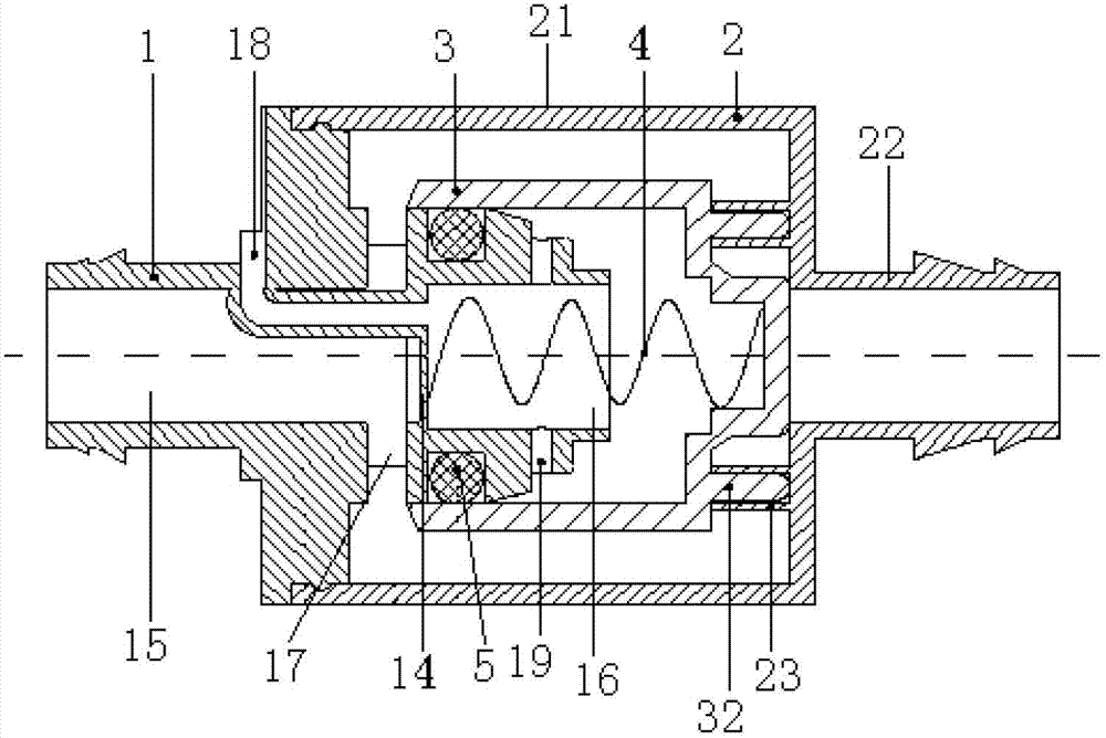
[0026] Such as figure 1 As shown, the present invention includes an upstream deflector 1 , a downstream housing 2 , a pressure regulating assembly 3 and a spring 4 .

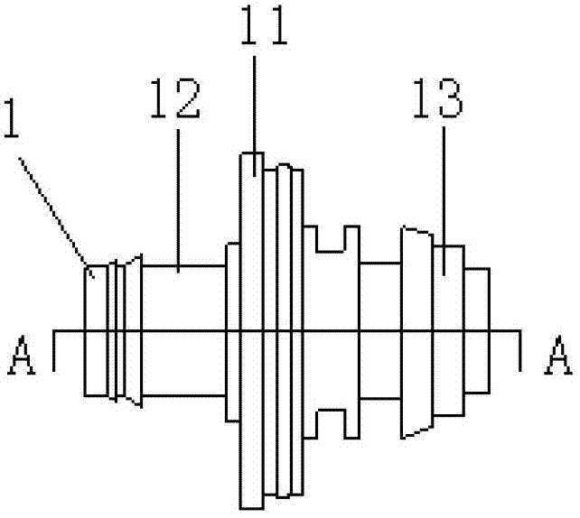
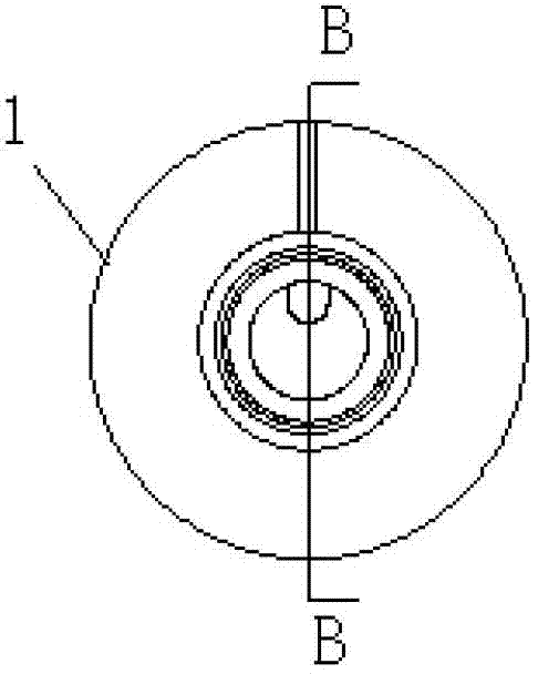
[0027] Such as Figure 1~5 As shown, the upstream guide body 1 of the present invention is a tubular structure, and a through hole is arranged axially inside it. The outer wall diameters of the upstream guide body 1 are different, the diameter at the middle position is large, the diameter at both ends is small, and the middle position is The casing connecting end 11, one of the two ends is used as the water inlet end 12, and the other end is used as the connecting end 13 of the pressure regulating assembly. A barrier 14 is arranged inside the upstream guide body 1 . The barrier 14 is located behind the shell connection end 11 and divides the inside of the upstream guide body 1 into an upper cavity 15 and a lower cavity 16 that are not connected to each other. On the circumferential side wall of the upper cavit...

Embodiment 2

[0035] Such as Figure 12 As shown, the difference between Embodiment 2 and Embodiment 1 is that: the downstream housing 2 includes a first cylinder 21 with the same diameter as the housing connection end 11 of the upstream guide body 1 , and the end of the first cylinder 21 Connect the side wall of the second cylindrical body 22, the central axis of the first cylindrical body 21 is perpendicular to the central axis of the second cylindrical body 22; 21 is a through hole connected inside, and the diameter of the through hole is the same as the inner diameter of the first cylindrical body 21; both ends of the second cylindrical body 22 are water outlets, and the outer wall of the water outlet can be set as a screw lock form. Two symmetrical positioning holes 23 are arranged on the inner wall of the second cylindrical body 22 at intervals. The pressure regulating assembly 3 is arranged in the first cylindrical body 21 and the second cylindrical body 22 . In the initial state ...


PUM


Abstract

The invention relates to a capillary pressure regulator. The capillary pressure regulator is characterized by comprising an upstream flow deflector, a downstream shell, a pressure regulating assembly and a spring, wherein a baffle for dividing interior of the upstream flow deflector into an upper cavity and a lower cavity which are not communicated with each other is arranged inside the upstream flow deflector; a water outlet hole is formed in the upper cavity; an air guiding pipe communicated with atmosphere is arranged on the lower cavity; a plurality of vent holes are also formed in the lower cavity; the downstream shell comprises a first cylinder body and a second cylinder body; the end part of the first cylinder body is connected with a shell connecting end of the upstream flow deflector; a plurality of positioning holes are formed in the side wall of the first cylinder body; the pressure regulating assembly is a cylindrical cavity with one opened side and one closed side; an outwardly-protruding spring installing groove is formed in the inner wall of a closed end; a positioning probe corresponding to the positioning holes is arranged on the outer wall of the closed end; the opened end of the pressure regulating assembly is connected with a pressure regulating assembly connecting end of the upstream flow deflector; a water stopping part is arranged between the opened end of the pressure regulating assembly and the pressure regulating assembly connecting end of the upstream flow deflector; and one end of the spring is pressed against the baffle inside the upstream flow deflector; and the other end of the spring is pressed against the bottom of the spring installing groove of the pressure regulating assembly.

Description

technical field [0001] The invention relates to a pressure regulator in the field of agricultural water-saving irrigation, in particular to a capillary pressure regulator. Background technique [0002] Irrigation uniformity is an important indicator for evaluating the performance of drip irrigation systems. However, due to the different distances between the pipes and the head of the system and the undulations of the terrain, the inlet pressures of different branch pipe inlets and different capillary pipe inlets vary greatly, which leads to water discharge from field drippers. Uneven flow affects the uniformity of irrigation in the drip irrigation system. In order to effectively control the irrigation uniformity of the drip irrigation system, the existing technical solutions are pressure regulation and flow regulation. [0003] The research on pressure regulators in our country started relatively late, and the research is more focused on branch pressure regulators. Althoug...

Claims


Application Information

Patent Timeline
Patent Type & Authority Applications(China)
IPC IPC(8): A01G25/02
Inventor 李光永齐成红
Owner CHINA AGRI UNIV
Why Eureka
Try Eureka