A compressor suction pipe and its manufacturing method and application

A compressor and suction pipe technology, applied in the field of compressors, can solve the problems of secondary melting of solder, vibration, poor quality, etc.

Active Publication Date: 2016-05-04
DONGGUAN JINRUI HARDWARE PROD
View PDF4 Cites 0 Cited by
  • Summary
  • Abstract
  • Description
  • Claims
  • Application Information

AI Technical Summary

Problems solved by technology

"The connection between the copper pipe and the iron pipe of the suction outer pipe is socketed and then welded through the stretching part arranged in a figure-eight shape, which leads to the complexity of the connection structure between the copper pipe and the iron pipe ; Moreover, since copper pipes and iron pipes are socketed furnace welded (also known as seam welding), vibration and cracking will occur during welding, which cannot meet the industry's requirements for the cleanliness of copper pipes, and When the air conditioner manufacturer re-solders, it is easy to cause the secondary melting of the solder, making the quality poor; moreover, because the copper pipe and the iron pipe are fitted with a socket-type gap before welding, the gap is filled with solder. If there are defects between welds, welding defect detection is also required
At the same time, it is not environmentally friendly due to the use of solder

Method used


Image

  • A compressor suction pipe and its manufacturing method and application
  • A compressor suction pipe and its manufacturing method and application
  • A compressor suction pipe and its manufacturing method and application

Examples


Embodiment 1

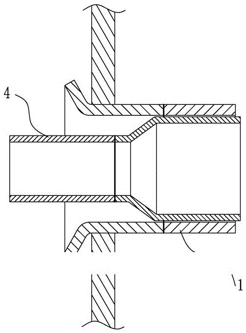
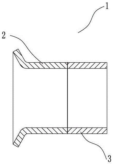
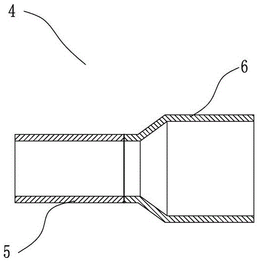
[0036] One of the specific implementations of a compressor suction pipe of the present invention, such as figure 1 , figure 2 and image 3 As shown, the compressed suction pipe includes an inner suction pipe 4 and an outer suction pipe 1, the inner suction pipe 4 includes a first inner pipe 5 and a second inner pipe 6, and the inner suction pipe 4 is a stepped pipe , wherein the small end is the first inner tube 5, the large end is the second inner tube 6, and among the butt ends of the first inner tube 5 and the butt ends of the second inner tube 6, the inner diameter of one of the butt ends is smaller than that of the other butt end Outer diameter, the first inner tube 5 is a copper-plated tube or iron tube, the second inner tube 6 is any one of copper-plated tube, copper tube and iron tube, preferably, the first inner tube 5 and the second inner tube 6 are all copper-plated tubes; the suction outer tube 1 includes a first outer tube 2 and a second outer tube 3, and among...

Embodiment 2

[0046] The second specific embodiment of a compressor suction pipe of the present invention, as Figure 4 As shown, the main technical solutions of this embodiment are the same as those of Embodiment 1, and the features not explained in this embodiment are explained in Embodiment 1, and will not be repeated here. The difference between this embodiment and Embodiment 1 is that the suction inner tube 4 is a conical tube, wherein the small end is the first inner tube 5 and the big end is the second inner tube 6 .

Embodiment 3

[0048] The third specific embodiment of a compressor suction pipe of the present invention, as Figure 5 As shown, the main technical solutions of this embodiment are the same as those of Embodiment 1, and the features not explained in this embodiment are explained in Embodiment 1, and will not be repeated here. The difference between this embodiment and Embodiment 1 is that the suction inner tube 4 is a cylindrical tube.


PUM


Abstract

The invention relates to the field of a compressor, in particular to a compressor air suction pipe and a manufacturing method and application of the compressor air suction pipe. The compressor air suction pipe comprises an air suction outer pipe and an air suction inner pipe, wherein the air suction outer pipe comprises a first outer pipe and a second outer pipe, and the first outer pipe and the second outer pipe are in butt welding through flash welding; and the air suction inner pipe comprises a first inner pipe and a second inner pipe, and the first inner pipe and the second inner pipe are in butt welding through flash welding. The manufacturing method of the compressor air suction pipe comprises preheating and upset-forging. The compressor air suction pipe is applied to optional one of an air conditioning compressor, a refrigerator compressor and a scroll compressor. According to the compressor air suction pipe manufactured by adopting the manufacturing method, the welding materials are saved, the production cost is reduced, and the environment-friendly production process without waste gas is ensured as well.

Description

technical field [0001] The invention relates to the field of compressors, in particular to a compressor suction pipe and its manufacturing method and application. Background technique [0002] The compressor is a fluid machine that raises low-pressure gas to high-pressure gas. It is the heart of the refrigeration system. There is a cylinder inside the shell of the compressor. When working, the low-temperature and low-pressure refrigerant gas enters the cylinder from the intake pipe, and the cylinder After it is compressed, high-temperature and high-pressure refrigerant gas is discharged from the exhaust pipe to provide power for the refrigeration cycle, thereby realizing the refrigeration cycle of compression→condensation→expansion→evaporation. During the operation of the system, it is impossible to guarantee that the refrigerant can be completely vaporized during the evaporation stage. In order to avoid the liquid refrigerant coming out of the evaporator from entering the c...

Claims


Application Information

Patent Timeline
Patent Type & Authority Patents(China)
IPC IPC(8): F04B39/12F16L13/02B23K11/04
Inventor 陈金龙
Owner DONGGUAN JINRUI HARDWARE PROD
Why Eureka
Try Eureka