High-power laser diode heat sink

A laser diode and high-power technology, applied in the direction of lasers, laser components, semiconductor lasers, etc., can solve problems affecting the output light performance and quality of laser diodes, increase the difficulty of heat sink design, and limit machining processes, etc., to achieve Get rid of the use of glue, avoid uneven lighting, and ensure cooling efficiency

Inactive Publication Date: 2012-06-13
SHANGHAI INST OF OPTICS & FINE MECHANICS CHINESE ACAD OF SCI
View PDF0 Cites 0 Cited by
  • Summary
  • Abstract
  • Description
  • Claims
  • Application Information

AI Technical Summary

Problems solved by technology

[0003] At present, in most cases, the cooling heat sink of the laser diode adopts the method of liquid inflow and outflow at the same time. It can be used when the temperature requirement of the laser diode is not high. If the requirement is relatively high, this method is not suitable. Because the liquid flowing in one direction will cause a temperature gradient, the laser diode also has a temperature gradient, which will affect the performance and quality of the output light of the laser diode
In addition, the position of the laser diode electrode makes the design of the heat sink more difficult, and is limited by the machining process. At present, metal adhesives are often used to bond two discrete laser diode heat sink components together, which makes it difficult to ensure an airtight structure. , if there is a gap in the bonding, the cooling liquid will seep out and the laser diode will be short-circuited, resulting in heavy losses

Method used


Image

  • High-power laser diode heat sink
  • High-power laser diode heat sink
  • High-power laser diode heat sink

Examples


Embodiment Construction

[0026] The present invention will be further described below in conjunction with the accompanying drawings and embodiments. But it should not limit the protection scope of the present invention.

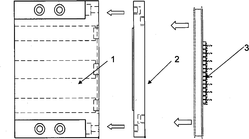
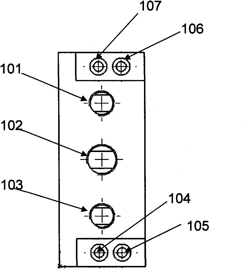
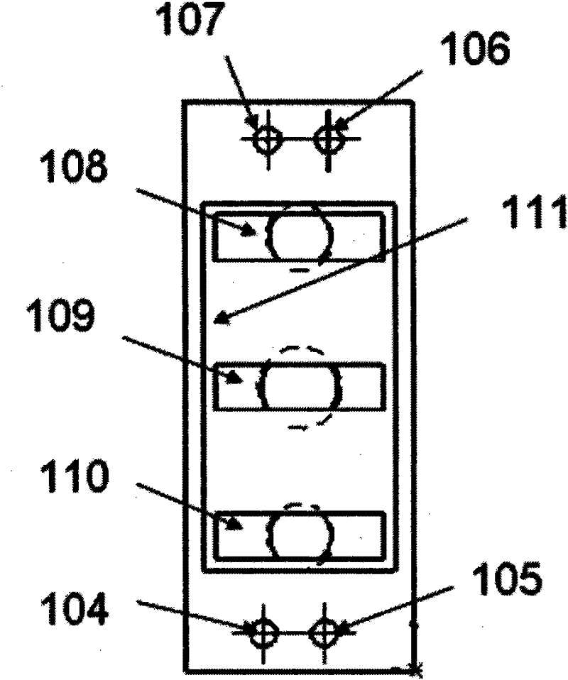
[0027] see first figure 1 , figure 1 It is an exploded view of the connection structure of the high-power laser diode heat sink and the laser diode module of the present invention, figure 2 It is the left view of the first module of the high-power laser diode heat sink of the present invention, image 3 It is the right view of the first module of the high-power laser diode heat sink of the present invention, Figure 4 It is a cross-sectional view of the module of the high-power laser diode heat sink of the present invention. Figure 5 It is the left view of the second module of the high-power laser diode heat sink of the present invention. Image 6 It is the right view of the second module of the high-power laser diode heat sink of the present invention. Figure 2 to Figure 6 ...


PUM


Abstract

The invention relates to a high-power laser diode heat sink which comprises a first module and a second module, wherein the first module and the second module are connected together, a pressure ring limiting slot for placing a pressure ring is arranged at the periphery of the middle part of the inner side of the first module, and a first rectangular groove, a second rectangular groove and a thirdrectangular groove are sequentially transversely arranged in the pressure ring limiting slot and respectively communicated with a first liquid inlet channel, a liquid outlet channel and a second liquid inlet channel which are respectively arranged at the upper end, in the middle and at the lower end of the outer side of the first module and used for the inlet and the outlet of a cooling liquid; amicrochannel is longitudinally arranged at the middle part of the inner side of the second module, the microchannel is laminated with the inner side of the first module and respectively communicated with the first rectangular groove, the second rectangular groove and the third rectangular groove, and a structure for the attachment of a laser diode module is arranged at the outer side of the second module. The invention can satisfy the requirement of high-power laser diode array cooling and improves the safety of laser diode cooling.

Description

technical field [0001] The invention relates to a laser diode, in particular to a high-power laser diode heat sink. Background technique [0002] With the maturity of laser diode technology and the irreplaceable advantages of laser diodes in pumping sources, the use of laser diodes is becoming more and more widespread. Laser oscillators and amplifiers, especially laser amplifiers, require more and more power for laser diodes. At present The single peak power has reached about 400w. A number of laser diodes form a laser diode array module to meet the energy demand. While generating the required high-energy pump light, a large amount of waste heat will inevitably be generated. Therefore, a suitable high-efficiency heat sink is required to cool the laser diode and ensure the temperature of the laser diode. Stability, to avoid changes in laser diode performance (such as center wavelength drift, divergence angle changes, etc.) caused by laser diode temperature drift. [0003] A...

Claims


Application Information

Patent Timeline
Patent Type & Authority Patents(China)
IPC IPC(8): H01S5/024
Inventor 施翔春张振华王建磊李磊
Owner SHANGHAI INST OF OPTICS & FINE MECHANICS CHINESE ACAD OF SCI
Why Eureka
Try Eureka