Casting cooling device

A cooling device and casting technology, applied in furnaces, heat treatment equipment, heat treatment furnaces, etc., can solve the problems of low air-cooled cooling efficiency, high scrap rate, poor quality of pure water-cooled cooling, etc., and achieve uniform cooling and improved cooling efficiency. Effect

Inactive Publication Date: 2019-11-26
NINGBO XIAYI ELECTROMECHANICAL TECH CO LTD
View PDF0 Cites 0 Cited by
  • Summary
  • Abstract
  • Description
  • Claims
  • Application Information

AI Technical Summary

Problems solved by technology

[0003] The purpose of the present invention is to overcome the defects of low cooling efficiency of pure air cooling and poor cooling quality of pure water cooling in the prior art, resulting in high reject rate, so as to realize a continuous cooling, high cooling efficiency and good cooling quality. Cooling device for casting

Method used


Image

  • Casting cooling device

Examples


Embodiment

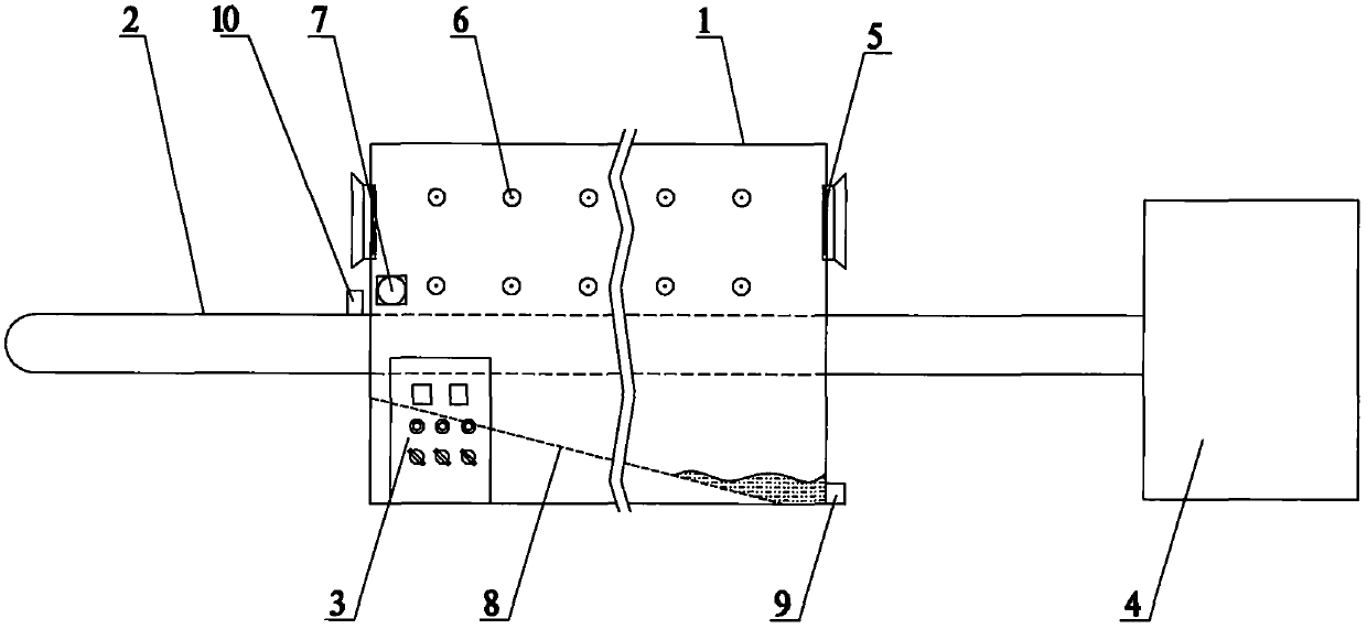
[0014] The cooling device for castings of the present invention includes a cooling box 1, a conveyor belt 2 and a control box 3, the cooling box 1 is a sealed box structure, and the conveyor belt 2 passes through the cooling box 1 along the length direction of the cooling box 1 One end of the conveyor belt 2 is connected to the annealing furnace 4, the control box 3 is arranged at one end of the bottom of the cooling box 1, the conveyor belt 2 is a steel mesh conveyor belt, and the two ends of the cooling box 1 are respectively provided with convection fans 5, and The rotation directions of the two convection fans 5 are consistent, so that the airflow in the cooling box 1 runs against the moving direction of the conveyor belt 2; the inner walls of both sides above the conveyor belt 2 in the cooling box 1 are provided with atomizing nozzles 6 in a straight line, A temperature sensor 7 is arranged on the side wall next to the atomizing nozzle 6 at the outlet end of the cooling bo...


PUM


Abstract

The invention relates to the field of automobile part production, in particular to a casting cooling device. The casting cooling device comprises a cooling box, a conveyer belt and a control cabinet.The cooling box is of a sealed box structure. The conveying belt passes through the cooling box in the length direction of the cooling box. One end of the conveyer belt is connected with an annealingfurnace. The control cabinet is arranged at one end of the bottom of the cooling box. The conveyer belt is a steel wire mesh conveyer belt. The two ends of the cooling box are provided with convectionfans. The rotation directions of the two convection fans are identical. The inner walls on the two sides in the cooling box are both provided with atomizing sprayers which are linearly and evenly distributed above the conveyer belt. A temperature sensor is arranged on the side wall at the outlet end of the cooling box and located on one side of the atomizing sprayer. The casting cooling device achieves continuous cooling of the casting and greatly improves cooling efficiency; and besides, a casting is not prone to cracking, cooling is uniform, and the cooling quality of the casting is greatlyimproved.

Description

technical field [0001] The invention relates to the field of auto parts production, in particular to a cooling device for castings. Background technique [0002] With the development of contemporary social economy, the demand for automobiles is increasing day by day, and the automobile manufacturing industry is developing. The production of auto parts is a complicated process, some of which are castings, and the castings of automobiles need to be cooled after they are finished. Only after treatment can the next process be carried out, but at present, most of the cooling of auto parts castings adopts simple air cooling, the cooling speed is slow, which cannot meet the requirements of automobile manufacturers, and some use water cooling, pure water cooling will cause the temperature of castings Unevenness leads to cracking, which greatly increases the scrap rate and greatly reduces the cooling quality, and some cooling devices are turned on and off when needed, so continuous c...

Claims


Application Information

Patent Timeline
Patent Type & Authority Applications(China)
IPC IPC(8): C21D9/00
CPCC21D9/0062
Inventor 孙波
Owner NINGBO XIAYI ELECTROMECHANICAL TECH CO LTD
Why Eureka
Try Eureka