Medical Burn Escarcer

A technology of dermabrasion device and casing, which is applied in the field of medical dermabrasion device for burns, which can solve the problems of poor patient experience and high heat generation, and achieve the effects of improving experience, reducing weight, and being convenient to hold

Active Publication Date: 2021-05-11
CHONGQING MEDICAL & PHARMA COLLEGE
View PDF10 Cites 1 Cited by
  • Summary
  • Abstract
  • Description
  • Claims
  • Application Information

AI Technical Summary

Problems solved by technology

[0006] The present invention intends to provide a kind of medical burn scab device, to solve the problem that the scab head of the existing scab device rotates rapidly under the drive of the motor, and rubs against the scab on the wound surface, which will generate a large amount of heat, which makes the patient's The problem of poor experience

Method used


Image

  • Medical Burn Escarcer
  • Medical Burn Escarcer

Examples


Embodiment 1

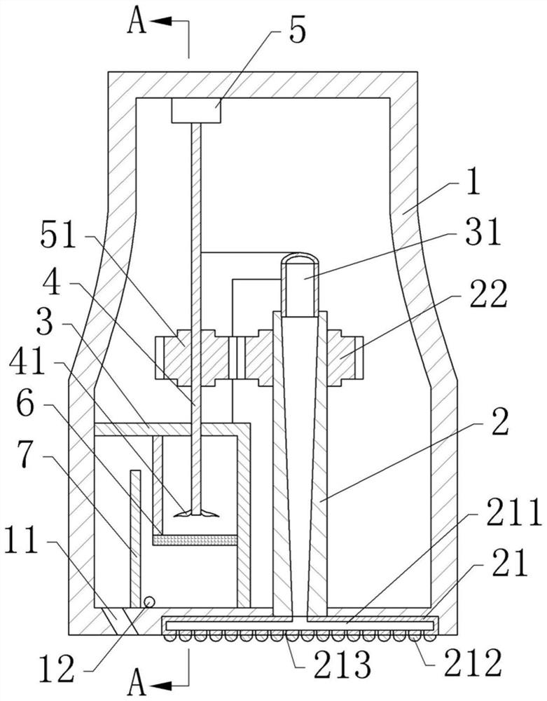
[0037] Medical burn scab device, basic as attached figure 1 As shown, it includes a casing 1, and the casing 1 is provided with a rotating shaft 4, a partition 3 and a rotating shaft 2 sequentially from left to right, and also includes a driving member for the electric rotating shaft 2 to rotate. The partition 3 is L-shaped, and the partition 3 divides the shell 1 into the air supply part on the left; The inner bottom wall is fixed, and the front and rear sides of the partition 3 are fixed to the inner walls of the front and rear sides of the casing 1 respectively, so that a sealed cavity is formed between the partition 3 and the left side of the casing 1 .

[0038] The rotating shaft 4 passes through the transverse portion of the partition plate 3 and is rotatably connected thereto, and the bottom of the rotating shaft 4 is fixed with cooling fins 41 . The rotating shaft 2 runs through the bottom of the casing 1 and extends to the outside of the casing 1, and the rotating sh...

Embodiment 2

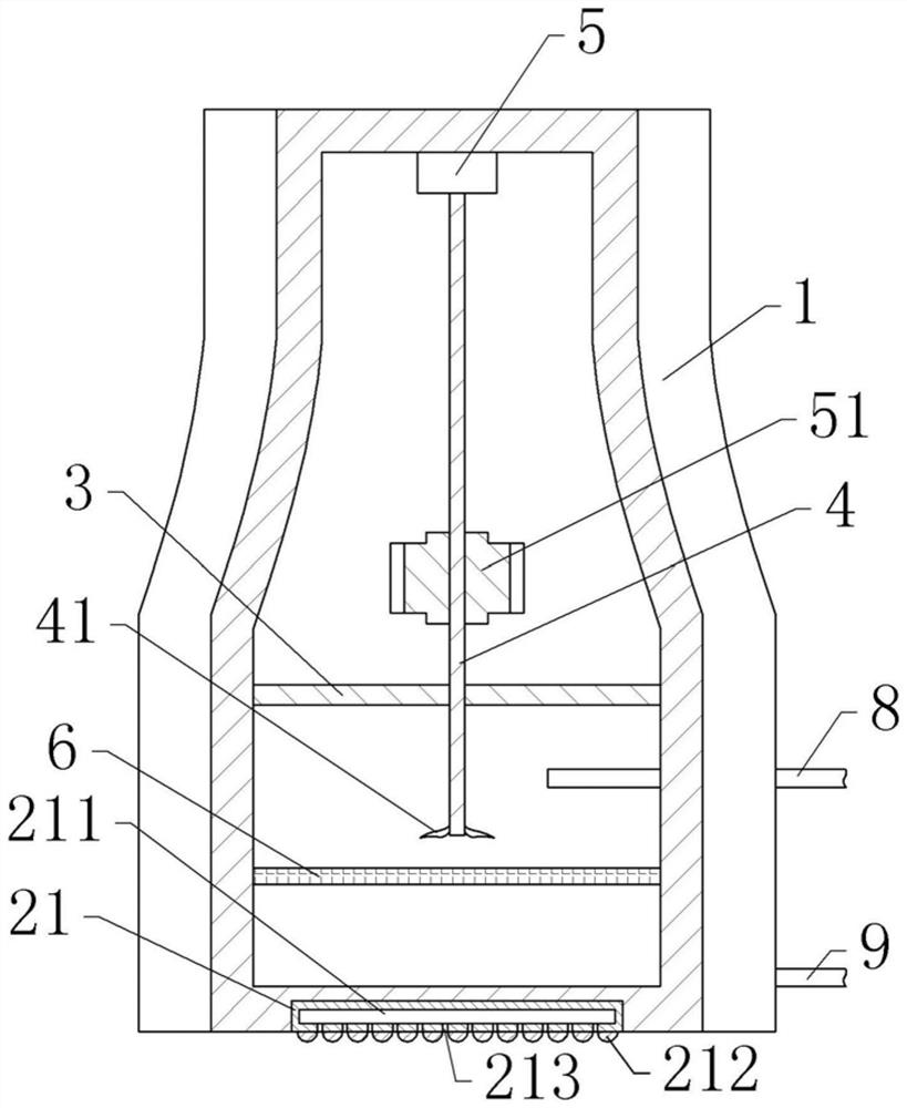
[0052] Embodiment 2 differs from Embodiment 1 only in that, as figure 2 As shown, in this embodiment, a liquid inlet pipe 8 and a liquid outlet pipe 9 are also provided, the liquid inlet pipe 8 runs through the left side wall of the housing 1, and the liquid inlet pipe 8 is located at the lateral part of the filter plate 6 and the lateral direction of the partition plate 3 Between the parts; the liquid outlet pipe 9 is inserted into the opening 12 to communicate with the sealed cavity. Both the liquid inlet pipe 8 and the liquid outlet pipe 9 are bellows, which can be stretched. When in use, the liquid inlet pipe 8 is communicated with the liquid storage tank, and the liquid outlet pipe 9 is communicated with the collection tank, so that the liquid can be introduced into the shell 1 to settle the debris, and the settled liquid can be drained away at the same time.

[0053] The specific implementation process is as follows:

[0054] When the rotating shaft 4 rotates to inhal...


PUM


Abstract

The invention belongs to the technical field of surgical cutting aids, and discloses a medical burn eschar device, which includes a casing, a rotating shaft penetrating through the casing and connected in rotation with the casing, and a driving member for driving the rotating shaft to rotate, and the rotating shaft is located outside the casing One end of the grinding crust head is coaxially fixed, the rotating shaft is hollow, the grinding crust head is provided with a cavity connected with the hollow rotating shaft, and the working surface of the grinding crust head is provided with an air outlet connected with the cavity; the shell An air supply part communicating with the hollow rotating shaft is also provided inside. The invention solves the problem that the scrubbing head of the existing scrubbing device rotates rapidly under the drive of the motor and rubs against the scab on the wound surface to generate a large amount of heat, which makes the patient's experience poor.

Description

technical field [0001] The invention belongs to the technical field of surgical cutting auxiliary instruments, in particular to a medical burn eschar remover. Background technique [0002] During the recovery process of the burn wound, the secretions produced by the burn wound will form a hard scab layer on the surface of the wound, and after the scab of a large area of ​​the wound is scabbed, it is easy to form subscrub fluid on the wound, resulting in acute microscopic Circulatory disorders, when severe, can lead to serious infection, sepsis, secondary organ damage (renal failure, respiratory failure, intestinal dysfunction, etc.) and other situations that endanger the patient's life safety. And because the wound is incrusted, the medicine for external use on the wound is difficult to absorb, which has a strong impact on wound healing. In clinical treatment, it is often necessary to remove infected necrotic scabs in time, so wound scab removal and scab treatment are very ...

Claims


Application Information

Patent Timeline
Patent Type & Authority Patents(China)
IPC IPC(8): A61B17/32H02K7/116A61F7/00B01D50/00B01D46/42
CPCA61B17/32H02K7/116A61F7/0053B01D46/4218A61B2017/320004A61B2017/320008A61F2007/0064B01D46/72B01D50/60
Inventor 张兵钱王广孙志刚唐金李雪涛
Owner CHONGQING MEDICAL & PHARMA COLLEGE
Why Eureka
Try Eureka