Shifting stable combination valve of power shifting speed changer and shifting and pressure regulating system

A technology for power shifting and transmission, which is applied in the field of smooth shifting combined valve and shifting pressure regulating system, can solve the problems of large size, large shifting impact, complex structure, etc., achieve reasonable oil pressure change characteristics, improve shifting Quality, compact design

Inactive Publication Date: 2013-04-10
TONGJI UNIV +2
View PDF5 Cites 3 Cited by
  • Summary
  • Abstract
  • Description
  • Claims
  • Application Information

AI Technical Summary

Problems solved by technology

The actual operating performance of the existing shift smooth coupling valve is not ideal. It often requires a large enough accumulator or a small orifice to cooperate to achieve the required smooth coupling time, and the oil pressure change law of the smooth coupling process is very important Buffer shift shock is not ideal
As a result, the existing shifting smooth combination valve often has the following problems: 1. The shifting impact is large; 2. The structure is complex and the size is large; 3. It is easy to cause fault phenomena such as throttle hole blockage and spring fatigue failure; 4. Parameter adjustment Difficult, not conducive to the generalization of products

Method used


Image

  • Shifting stable combination valve of power shifting speed changer and shifting and pressure regulating system
  • Shifting stable combination valve of power shifting speed changer and shifting and pressure regulating system
  • Shifting stable combination valve of power shifting speed changer and shifting and pressure regulating system

Examples


Embodiment Construction

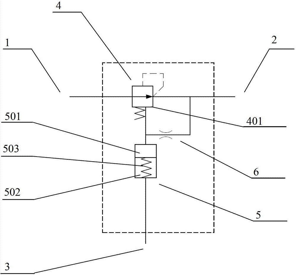
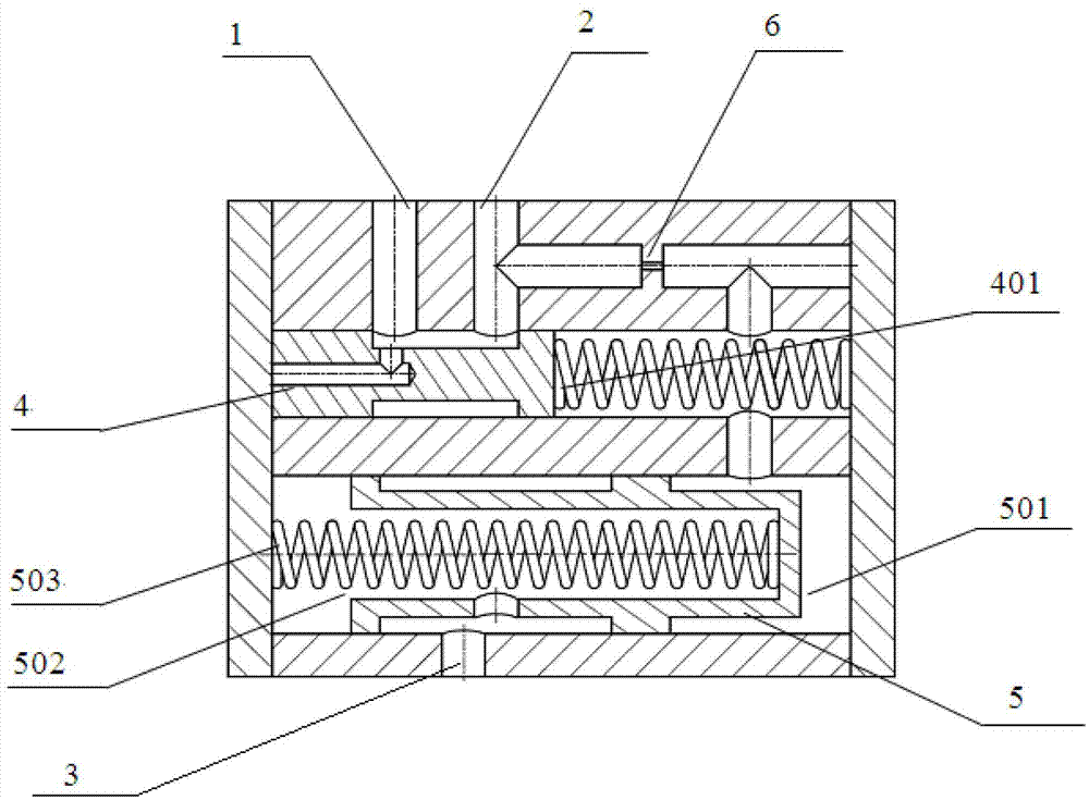
[0020] Such as figure 1 and image 3 As shown, a smooth shift combination valve 20 of a power shift transmission includes an oil inlet 1, an oil outlet 2, a control port 3 for controlling the pressure regulation process, a hydraulic control type pressure reducing valve 4, and an accumulator 5 and orifice 6. The hydraulically controlled pressure reducing valve 4 is connected in series between the oil inlet 1 and the oil outlet 2; the two ends of the orifice 6 are respectively connected with the liquid control port 401 of the pressure reducing valve and the oil outlet 3; the accumulator 5 includes The back cavity 501 and the power cavity 502, the back cavity 501 is connected to the hydraulic control port 401 of the pressure reducing valve, and the power cavity 502 is connected to the control port.

[0021] The oil in the main oil circuit enters through the oil inlet 1 and passes to the hydraulic control pressure reducing valve 4; the accumulator 5 is used as an energy storage ...


PUM


Abstract

The invention discloses a shifting stable combination valve of a power shifting speed changer and a shifting and pressure regulating system. The shifting stable combination valve comprises an oil inlet, an oil outlet, a control opening, a hydraulic control type pressure reducing valve, an energy accumulator and a throttling hole, wherein the control opening is used for controlling a pressure regulating system; the hydraulic control type pressure reducing valve is connected between the oil inlet and the oil outlet in series; two ends of the throttling hole are respectively connected with a hydraulic control opening end of the hydraulic control type pressure reducing valve and the oil outlet; and the energy accumulator comprises a back cavity and a power cavity, the back cavity is connected to the hydraulic control opening end of the hydraulic control type pressure reducing valve, and the power cavity is connected with the control opening. The shifting and pressure regulating system comprises a main throttling hole, the shifting stable combination valve, a hydraulic control valve and a pressure reducing valve. According to the shifting stable combination valve provided by the invention, the structural design is compact, the oil pressure variation characteristic is reasonable, and the shifting stable combination valve has an important practical value for reducing the shifting impact of the power shifting speed changer, improving the working environment of a driver, reducing the labor intensity, prolonging the service life of a transmission system component, and the like.

Description

technical field [0001] The invention relates to the technical field of walking machinery transmission, and in particular to a shifting stability combination valve and a shifting pressure regulating system in the technical field of engineering machinery transmission. Background technique [0002] In the field of mobile machinery, especially construction machinery transmission technology, power shift transmissions have been widely used. The power shift transmission for construction machinery has the characteristics of simple operation, fast shifting, and shifting without stopping under working load. This kind of transmission realizes shifting by hydraulically operating the clutch (or brake) to engage and disengage. Due to the incompressibility of the liquid, the hydraulic transmission system has a relatively high rigidity. It will rise instantaneously, which will have the following adverse consequences: (1) The clutch is engaged roughly, resulting in shifting shocks, causing ...

Claims


Application Information

Patent Timeline
Patent Type & Authority Applications(China)
IPC IPC(8): F16H61/06F16H61/4008
Inventor 刘钊王磊朱玉田王攀峰龚贤元
Owner TONGJI UNIV
Why Eureka
Try Eureka