
Laser circle measuring device and application method thereof

An application method and technology of a laser range finder, applied in the field of shield tunnel inspection, can solve the problems of high cost and stretched equipment, and achieve the effects of convenient angle control, low cost and simple installation.

Active Publication Date: 2013-04-10
SHANGHAI TUNNEL ENGINEERING RAILWAY TRANSPORTATION DESIGN INSTITUTE
View PDF7 Cites 11 Cited by
  • Summary
  • Abstract
  • Description
  • Claims
  • Application Information

AI Technical Summary

Problems solved by technology

[0003] In the existing technology, a high-precision professional section meter is used for measurement and its supporting professional section calculation software is used to process data. However, in view of the high cost of purchasing this kind of instrument, general items are not purchased, but only equipped with general functions. Total station, and the general cross-section calculation software also has certain limitations in its functions. Only when the design center position is known can the shield shell section be evaluated, and for shield shell roundness detection, the design circle center is not correct. Therefore, this kind of cross-section software also seems to be stretched in the implementation of shield shell roundness detection, so how to more accurately conduct shield shell roundness detection has become a thorny problem

Method used


Image

  • Laser circle measuring device and application method thereof
  • Laser circle measuring device and application method thereof
  • Laser circle measuring device and application method thereof

Examples


Embodiment

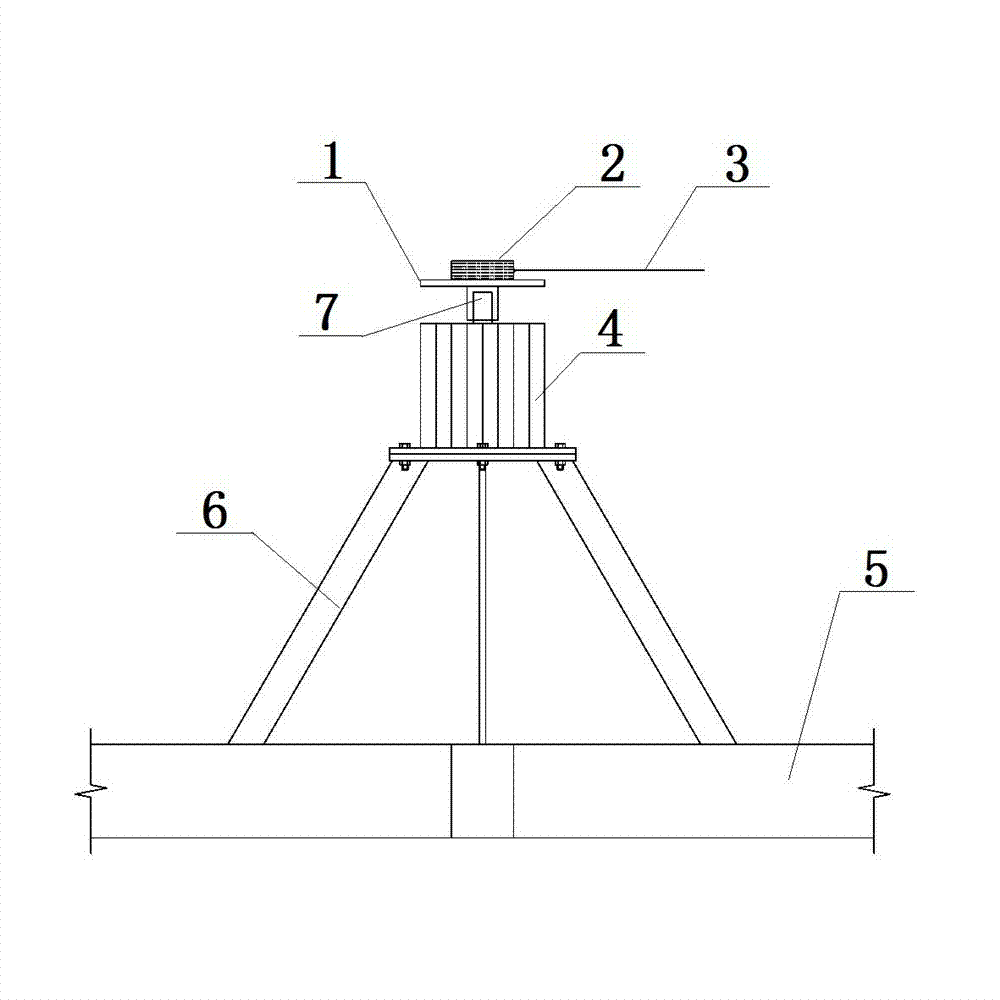
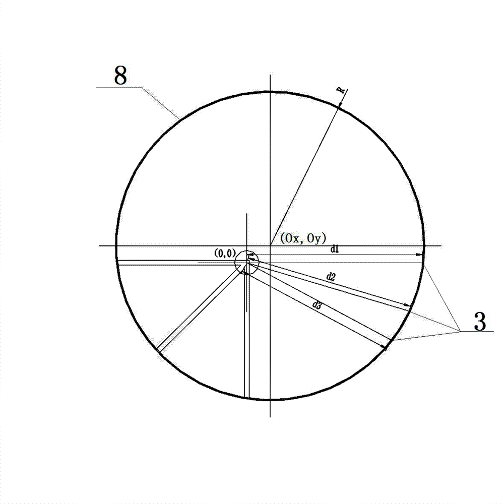
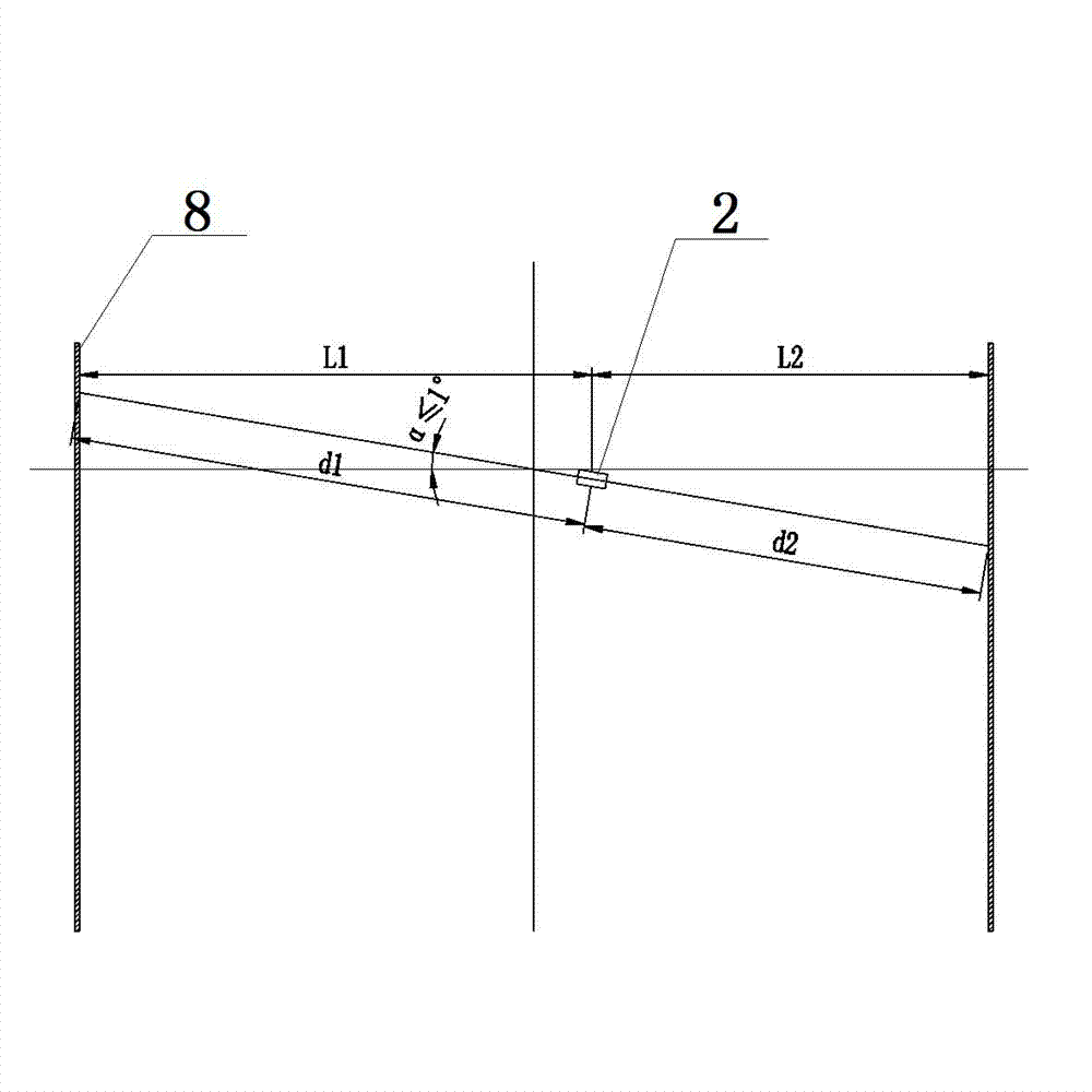
[0020] Example: such as figure 1 As shown, this embodiment specifically relates to a laser circle measuring device, which is suitable for data measurement of plane geometric shapes such as subways and tunnels. The laser circle measuring device is specifically composed of a support rod 5, a mounting bracket 6, a stepping motor 4, a supporting platform 1 and a laser rangefinder 2, and an axial slide rail is arranged on the inner wall of the shield shell 8, and the support rod 5 It is movably connected with the slide rail arranged on the inner wall surface of the shield shell 8, the vertical bisector of the support rod 5 coincides with the central axis of the shield shell 8, and the mounting frame 6, the stepping motor 4, the supporting platform 1 and the laser rangefinder 2 is axially arranged along the central axis of the shield shell 8 (that is, arranged on the vertical bisector of the support rod 5), wherein the installation bracket 6 and the support rod 5 are connected by bo...


PUM


Abstract

The invention belongs to the technical field of shield detecting, and particularly relates to a laser circle measuring device used for measuring circular degree of a shield shell and an application method of the laser circle measuring device. The laser circle measuring device comprises a supporting rod, a stepping motor fixed on the supporting rod and a laser distance measuring device fixed on a rotating shaft of the stepping motor. Two ends of the supporting rod are respectively arranged on the inner wall of the shield shell in a supporting mode, and the stepping motor and the laser distance measuring device are both arranged on a vertical halving line of the supporting rod. The vertical halving line is the direction of an axial lead of the shield shell. Then the laser distance measuring device is used as a gyration center, coordinates of points on the inner wall of the shield shell are measured at intervals of certain angles, and the circular degree of the shield shell is measured and calculated through a special prepared calculating method. The laser circle measuring device and the application method of the laser circle measuring device has the advantages that the laser circular measuring device is simple in installation, manufacturing cost is low, angle control is convenient and accurate during measurement, change of the circular degree of the shield shell in the axial direction can be measured, all data of the circular degree of the shield shell can be converted automatically through a computer processor, and accuracy is high.

Description

technical field [0001] The invention belongs to the technical field of shield tunneling detection, and in particular relates to a laser circle measuring device for measuring the roundness of a shield shell and an application method thereof. Background technique [0002] The basic working principle of the shield machine is that a cylindrical steel component is pushed forward along the tunnel axis to excavate the soil. The shell of the cylindrical steel assembly is the shield shell, which acts as a temporary support for the excavated unlined tunnel section, bears the pressure of the surrounding soil layer, and assembles the segments under the protection of the shield shell to form a permanent lining . The roundness of the shield shell during assembly will directly affect the quality of the segment assembly in the future and the control and orientation of the shield attitude during the excavation process. Therefore, the surveyors should obtain the roundness of the shield shell...

Claims


Application Information

Patent Timeline
Patent Type & Authority Applications(China)
IPC IPC(8): G01B11/24
Inventor 宋振华祝平朱中意
Owner SHANGHAI TUNNEL ENGINEERING RAILWAY TRANSPORTATION DESIGN INSTITUTE
Learn More