
Pattern generators comprising a calibration system

A technology of pattern generation and calibration system, applied in instruments, photoengraving process of pattern surface, optics, etc., can solve problems such as difficulties

Active Publication Date: 2013-04-10
MICRONIC LASER SYST AB
View PDF5 Cites 4 Cited by
  • Summary
  • Abstract
  • Description
  • Claims
  • Application Information

AI Technical Summary

Problems solved by technology

However, in at least some cases, it is somewhat difficult to perform pattern matching with sufficient accuracy and / or to determine with sufficient accuracy the positions of pixels in the pattern to be generated on the workpiece.

Method used


Image

  • Pattern generators comprising a calibration system
  • Pattern generators comprising a calibration system
  • Pattern generators comprising a calibration system

Examples


Embodiment Construction

[0049] Example embodiments will now be described more fully with reference to the accompanying drawings, in which some example embodiments are shown. In the drawings, the thicknesses of layers and regions are exaggerated for clarity. Like reference numerals in the drawings indicate like elements.

[0050] Detailed exemplary embodiments are disclosed herein. However, specific structural and functional details disclosed herein are merely representative for purposes of describing example embodiments. The example embodiments may be embodied in many alternative forms and should not be construed as limited to only the example embodiments set forth herein.

[0051] It should be understood, however, that there is no intention to limit exemplary embodiments to the particular few disclosed, but on the contrary, exemplary embodiments are to cover all modifications, equivalents, and other modifications falling within the appropriate range. plans and alternatives. Like numerals refer t...


PUM


Abstract

A pattern generator includes: a writing tool and a calibration system. The writing tool is configured to generate a pattern on a workpiece arranged on a stage. The calibration system is configured to determine a correlation between a coordinate system of the writing tool and a coordinate system of a calibration plate on one of the stage and the workpiece. The calibration system is also configured to determine the correlation at least partly based on an optical correlation signal, or pattern, in a form of at least one optical beam being reflected from at least one reflective pattern on the surface of the calibration plate.

Description

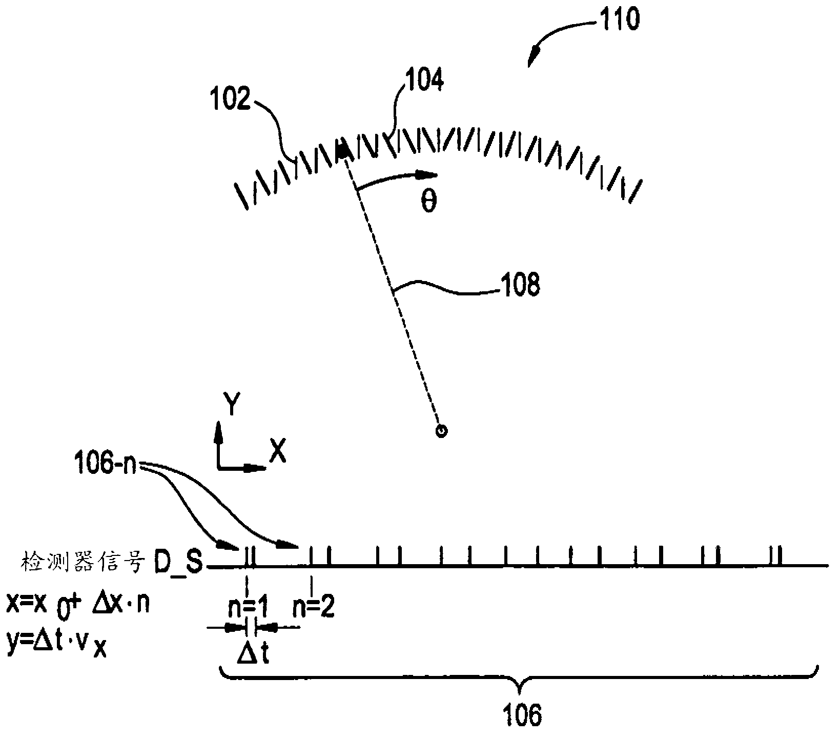
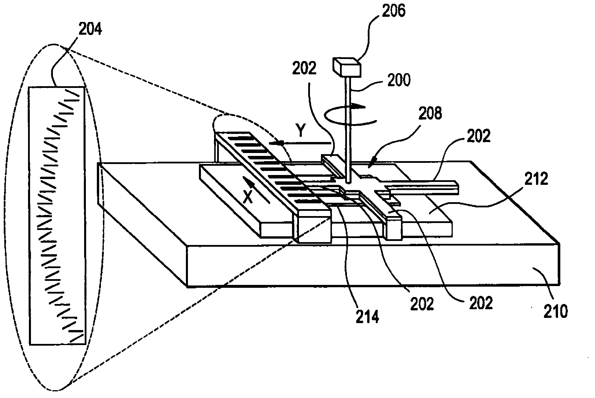
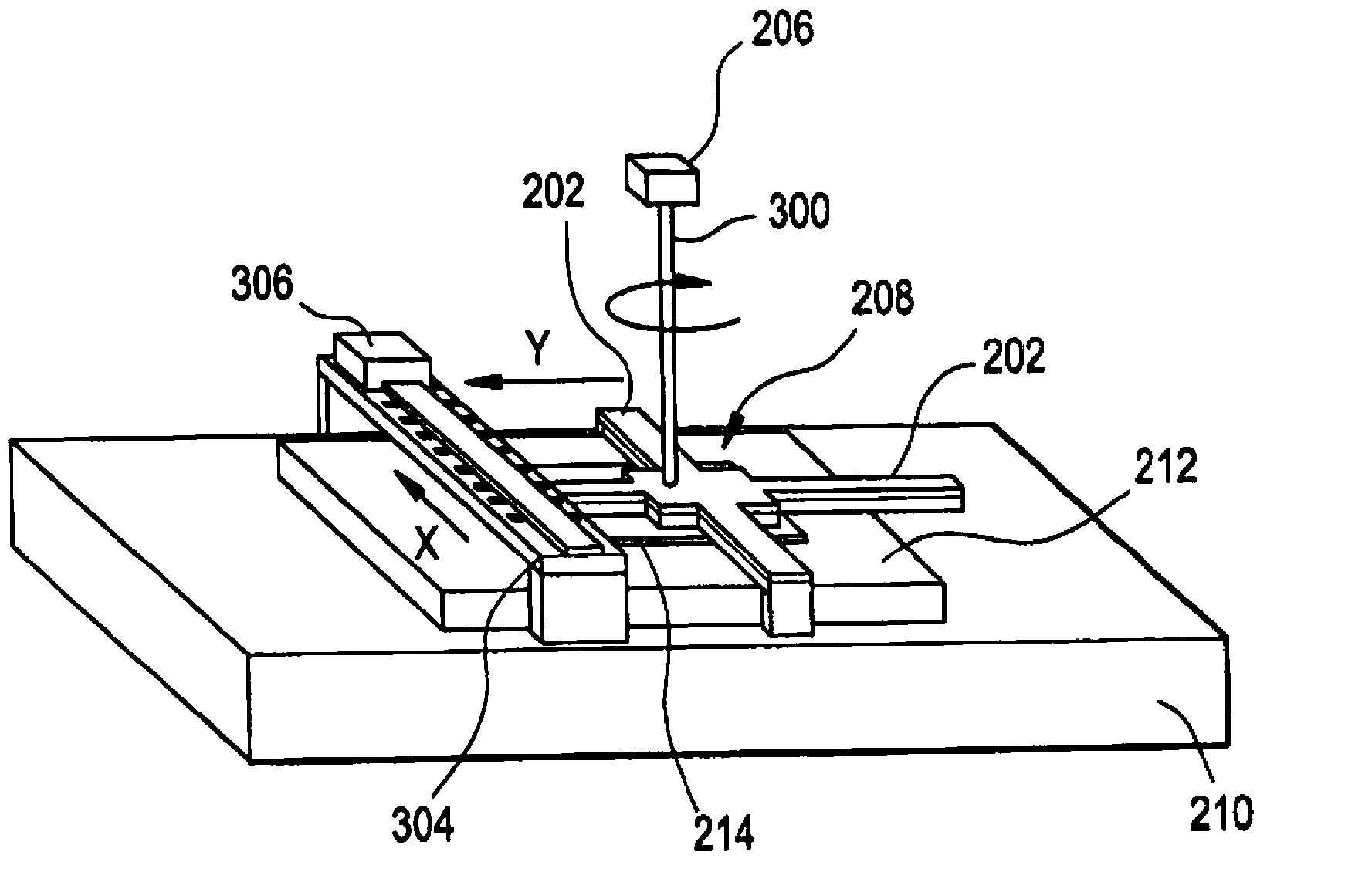
[0001] related application [0002] This PCT patent application claims priority to Provisional US Patent Application no. 61 / 282,584, filed March 3, 2010. Background technique [0003] Pattern matching is useful in performing fast real-time alignment when forming a pattern on a workpiece. However, in at least some cases, it can be somewhat difficult to perform sufficiently accurate pattern matching and / or determine with sufficient accuracy the positions of pixels in the pattern to be generated on the workpiece. Contents of the invention [0004] Exemplary embodiments describe a pattern generator including a calibration system configured to determine a correlation between a coordinate system of a writing tool and a coordinate system of a calibration plate based at least in part on a light beam reflected from a calibration plate . [0005] According to at least some example embodiments, the calibration system is configured to determine, based at least in part on at least one ...

Claims


Application Information

Patent Timeline
IPC IPC(8): G03F7/20G03F9/00
CPCG03F7/70775G03F7/7085G03F9/7049G03F9/7076G03F9/00G03F7/20G03F9/7019
Inventor A.斯文森F.琼森
Owner MICRONIC LASER SYST AB
Learn More