Optical System and Assembly Method

a technology of optical system and assembly method, which is applied in the direction of manufacturing tools, furniture parts, instruments, etc., can solve the problems of high cost of ownership for theater owners, high cost of electricity, and high cost of image projecting on the screen, and achieve the effect of long operation li

Inactive Publication Date: 2010-10-07
PROJECTION VENTURES INC
View PDF50 Cites 113 Cited by
  • Summary
  • Abstract
  • Description
  • Claims
  • Application Information

AI Technical Summary

Benefits of technology

[0012]In summary, the main problems facing digital image projectors are providing a bright image with a long operation lifetime, especially in the case of stereoscopic systems, and providing an alignment and assembly method that is feasible in full-scale production.

Problems solved by technology

This is a highly inefficient source for projecting an image onto a screen due to the extended size of the source, its low brightness, its broadband light, and the relatively short lifetime of the lamp itself.
The cost of ownership to theater owners is large due to the frequent lamp changes required, the cost of electricity to operate the multi kilowatt lamps as well as the cooling required to keep the projector room at a normal operating temperature.
The move to digital cinema further reduces the efficiency of the lamp due to the requirement that the light needs to be separated into component red / green / blue bands to illuminate three modulation arrays in a uniform manner before recombining the beams for projection.
Solid-state lasers are not without problems, however.
The typical high purity TEM00 Gaussian spatial mode is difficult to convert to a uniform source over the digital modulators.
The narrow line width of a laser leads to speckle patterns over the viewed image which may lead to an unacceptable loss of image quality.
In manufacturing quantities of thousands or more, conventional optical assembly techniques do not provide cost-effective methods for assembling optical devices with high tolerances such as complex laser systems.
In summary, the main problems facing digital image projectors are providing a bright image with a long operation lifetime, especially in the case of stereoscopic systems, and providing an alignment and assembly method that is feasible in full-scale production.

Method used


Image

  • Optical System and Assembly Method
  • Optical System and Assembly Method
  • Optical System and Assembly Method

Examples


Embodiment Construction

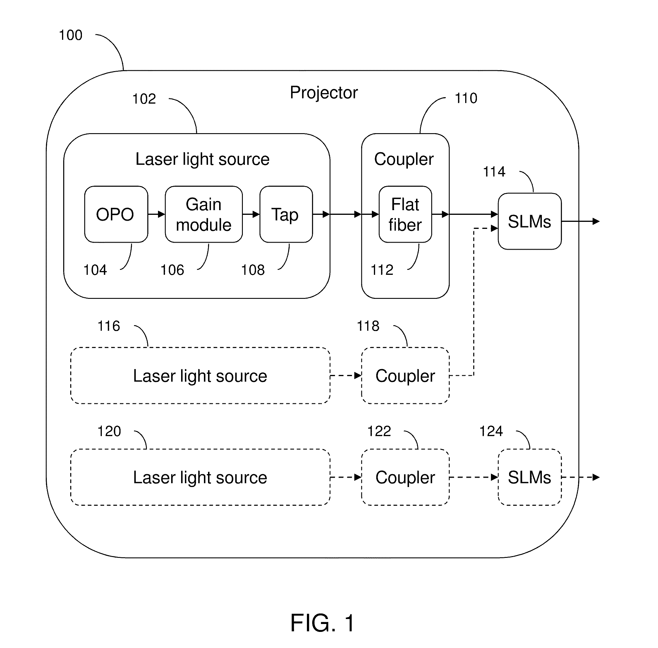
[0126]FIG. 1 is a block diagram of optical system 100 which has a number of novel parts that will be explained in the following description. First laser light source 102 may include OPO 104, laser gain module 106, and optical tap 108. Light is generated in OPO 104, passes through gain module 106, then through tap 108. The light then passes through first coupler 110 which includes flat-sided fiber 112, and then is processed by first SLMs 114. The light is then projected out of the optical system.

[0127]Second laser light source 116 may optionally be included for stereoscopic optical systems. The light from second laser light source 116 passes through second coupler 118 and then through first SLMs 114. The light is then projected out of the optical system. Alternatively, third laser light source 120 may optionally be included for stereoscopic optical systems. The light from third laser light source 120 passes through third coupler 122 and then through second SLMs 124. The light is then...


PUM

PropertyMeasurementUnit
wavelengthsaaaaaaaaaa

Abstract

An optical system which includes some or all of the following parts: a laser light source which illuminates a spatial light modulator such that optical characteristics are preserved; a stereoscopic display which has a polarization-switching light source; a stereoscopic display which includes two infrared lasers, two optical parametric oscillators, and six second harmonic generators; two light sources processed by two parts of the same spatial light modulator; a method of assembly using an alignment plate to align kinematic rollers on a holding plate; an optical support structure which includes stacked, compartmented layers; a collimated optical beam between an optical parametric oscillator and a second harmonic generator; a laser gain module with two retroreflective mirrors; an optical tap which keeps the monitored beam co-linear; an optical coupler which includes an optical fiber and a rotating diffuser; and an optical fiber that has a core with at least one flat side.

Description

BACKGROUND OF THE INVENTION[0001]Movie theaters have traditionally relied on projectors which use an arc-lamp as the source of light. This is a highly inefficient source for projecting an image onto a screen due to the extended size of the source, its low brightness, its broadband light, and the relatively short lifetime of the lamp itself. The cost of ownership to theater owners is large due to the frequent lamp changes required, the cost of electricity to operate the multi kilowatt lamps as well as the cooling required to keep the projector room at a normal operating temperature.[0002]The move to digital cinema further reduces the efficiency of the lamp due to the requirement that the light needs to be separated into component red / green / blue bands to illuminate three modulation arrays in a uniform manner before recombining the beams for projection. Finally, 3-D digital cinema requires even more light as the projected image must be alternated between scenes for the left and right e...

Claims


Application Information

Patent Timeline
Patent Type & Authority Applications(United States)
IPC IPC(8): H04N13/04G02F1/00G02B27/26G02B27/22G02F1/37H01S3/094G02B17/00G02B27/48B23P11/00F16M13/00G02B30/25H04N13/363
CPCG02B27/1026Y10T29/49901G02B27/1073G02B27/145G02B27/149G02B27/26G02B27/286G02B27/48H01S3/005H01S3/0092H01S3/0606H01S3/0941H01S3/1611H01S3/2325H01S3/2383H01S3/2391H04N9/3105H04N9/3161H04N9/3197H04N13/0422H04N13/0425H04N13/0431H04N13/0434H04N13/0438H04N13/0459G02F1/3532G02B27/22G02F1/39G02F1/37G02B27/2264G02B27/1046H04N13/324H04N13/327H04N13/334H04N13/337H04N13/341H04N13/363G02B30/25G02B30/24H01S3/23
Inventor COPPETA, DAVID A.ZAMBUTO, JAMES J.TURNER, IANGOODWINBECK, WILLIAM
Owner PROJECTION VENTURES INC
Why Eureka
Try Eureka