Optical Coupler Devices, Methods of Their Production and Use

a technology of optical couplers and optical couplers, applied in the direction of instruments, cladded optical fibres, optical elements, etc., can solve the problem of insufficient control

Inactive Publication Date: 2007-10-11
CRYSTAL FIBRE AS
View PDF12 Cites 107 Cited by
  • Summary
  • Abstract
  • Description
  • Claims
  • Application Information

AI Technical Summary

Benefits of technology

[0219] In a particular embodiment, the optical coupler comprises at least one input fibre constituted by an optical fibre according to the embodiments described above under the heading ‘1. A mode field converting optical waveguide fibre’ and as defined in the corresponding claims or by an photonic crystal fibre according to the embodiments described above under the heading ‘2. An NA converting photonic crystal fibre’ and as defined in the corresponding claims. This has the advantage of providing a flexible scheme for controlling the spatial extension of the mode field of a guided mode of an optical coupler.

Problems solved by technology

The problem of the prior art is to provide a sufficiently precise control of the mode field diameter in a tapered waveguide.

Method used


Image

  • Optical Coupler Devices, Methods of Their Production and Use
  • Optical Coupler Devices, Methods of Their Production and Use
  • Optical Coupler Devices, Methods of Their Production and Use

Examples


Embodiment Construction

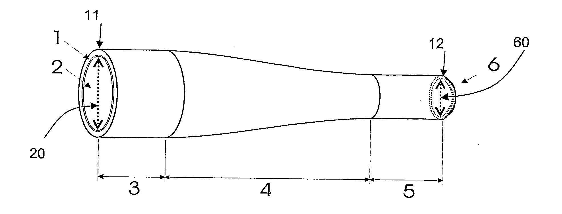
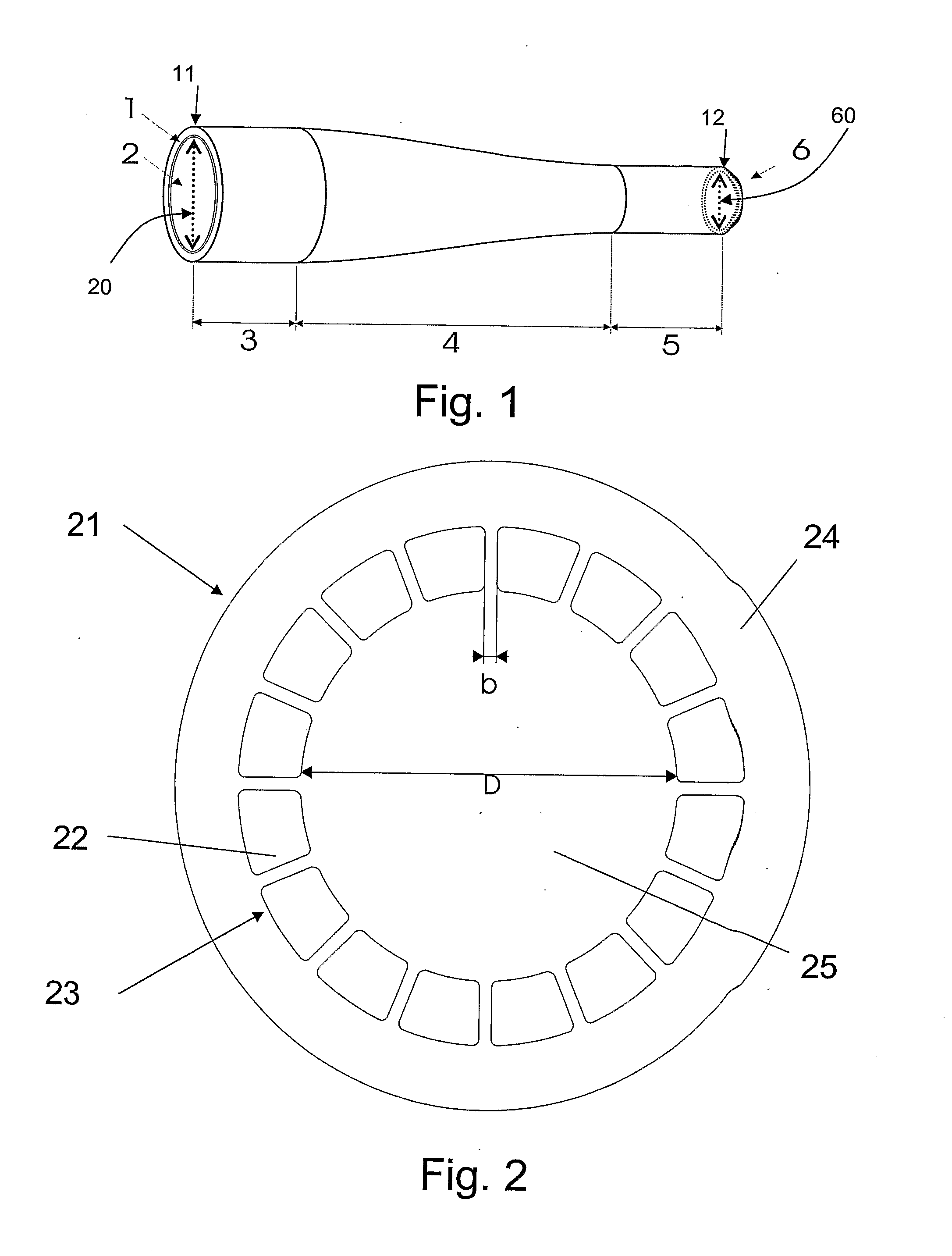
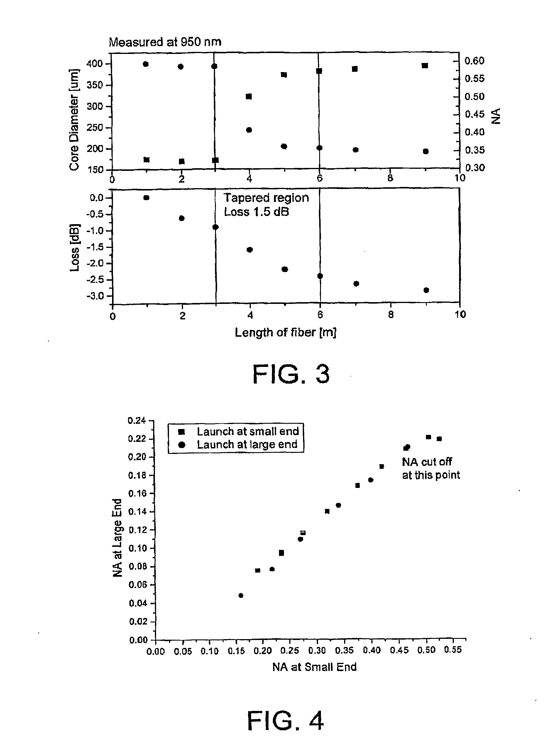
[0256] Optical components according to the present invention are typically in the form of optical fibre, i.e. flexible light guiding devices. The optical fibres have a longitudinal direction and a cross-section perpendicular thereto. The optical fibre comprises a number of longitudinally extending features that may vary in cross-sectional size along the fibre (a photonic crystal fibre). The variation is in the form of a tapering, providing larger cross sectional feature dimensions in a first fibre end than in a second fibre end. The optical fibre comprises an air-clad. An air-clad is in the present context taken to mean a cladding region comprising holes or voids that surrounds a multi-mode core. As the dimensions of the air-clad are reduced as the fibre is tapered down, the NA of the optical fibre is increased. This is used to provide coupling of light from a large spot / core size and a low NA to a small spot / core size with a high NA.

[0257] Most references to physical fibre paramet...


PUM


Abstract

The present invention relates in general to coupling of light from one or more input waveguides to an output waveguide or output section of a waveguide having other physical dimensions and/or optical properties than the input waveguide or waveguides. The invention relates to an optical component in the form of a photonic crystal fibre for coupling light from one component/system with a given numerical aperture to another component/system with another numerical aperture. The invention further relates to methods of producing the optical component, and articles comprising the optical component, and to the use of the optical component. The invention further relates to an optical component comprising a bundle of input fibres that are tapered and fused together to form an input coupler e.g. for coupling light from several light sources into a single waveguide. The invention still further relates to the control of the spatial extension of a guided mode (e.g. a mode-field diameter) of an optical beam in an optical fibre. The invention relates to a tapered longitudinally extending optical waveguide having a relatively larger cross section that over a certain longitudinal distance is tapered down to a relatively smaller cross section wherein the spatial extent of the guided mode is substantially constant or expanding from the relatively larger to the relatively smaller waveguide cross section. The invention may e.g. be useful in applications such as fibre lasers or amplifiers, where light must be coupled efficiently from pump sources to a double clad fibre.

Description

TECHNICAL FIELD [0001] The present invention relates in general to coupling of light from one or more input waveguides to an output waveguide or output section of a waveguide having other physical dimensions and / or optical properties than the input waveguide or waveguides. [0002] The present invention relates to an optical component in the form of a photonic crystal fibre for coupling light from one component / system with a given numerical aperture to another component / system with another numerical aperture. The invention further relates to methods of producing the optical component, and articles comprising the optical component, and to the use of the optical component. The present invention is based on properties of photonic crystal fibres (PCF). [0003] The present invention further relates to an optical component comprising a bundle of input fibres that are tapered and fused together to form an input coupler e.g. for coupling light from several light sources into a single waveguide...

Claims


Application Information

Patent Timeline
Patent Type & Authority Applications(United States)
IPC IPC(8): G02B6/14G02B6/02G02B6/036G02B6/26G02B6/28H01S3/067
CPCG02B6/02004H01S3/094019G02B6/02338G02B6/02357G02B6/02366G02B6/02376G02B6/03627G02B6/03644G02B6/03688G02B6/262G02B6/2835H01S3/06708H01S3/06729H01S3/06741H01S3/06745H01S3/094007G02B6/02333
Inventor NIELSEN, MARTIN DYBENDALSKOVGAARD, PETER M.W.BROENG, JESVIENNE, GUILLAUME
Owner CRYSTAL FIBRE AS
Why Eureka
Try Eureka