Fiber laser

a fiber laser and fiber technology, applied in the field of fiber lasers, can solve the problems of resin damage, resin damage, and above-mentioned conventions, and achieve the effect of improving the reliability of assembled fiber lasers

Active Publication Date: 2013-11-21
PANASONIC CORP
View PDF3 Cites 32 Cited by
  • Summary
  • Abstract
  • Description
  • Claims
  • Application Information

AI Technical Summary

Benefits of technology

[0017]The structure above allows unwanted light such as residual excitation light to gradually leak from a wide range in the section recoated with high refractive-index resin. Therefore, in spite of osci

Problems solved by technology

The conventional arts above, however, have the problems below.
If residual excitation light to be removed concentrates at a part recoated with such a high refractive-index resin, the resin can be damaged by heat.
In the case o

Method used


Image

  • Fiber laser
  • Fiber laser
  • Fiber laser

Examples


first exemplary embodiment

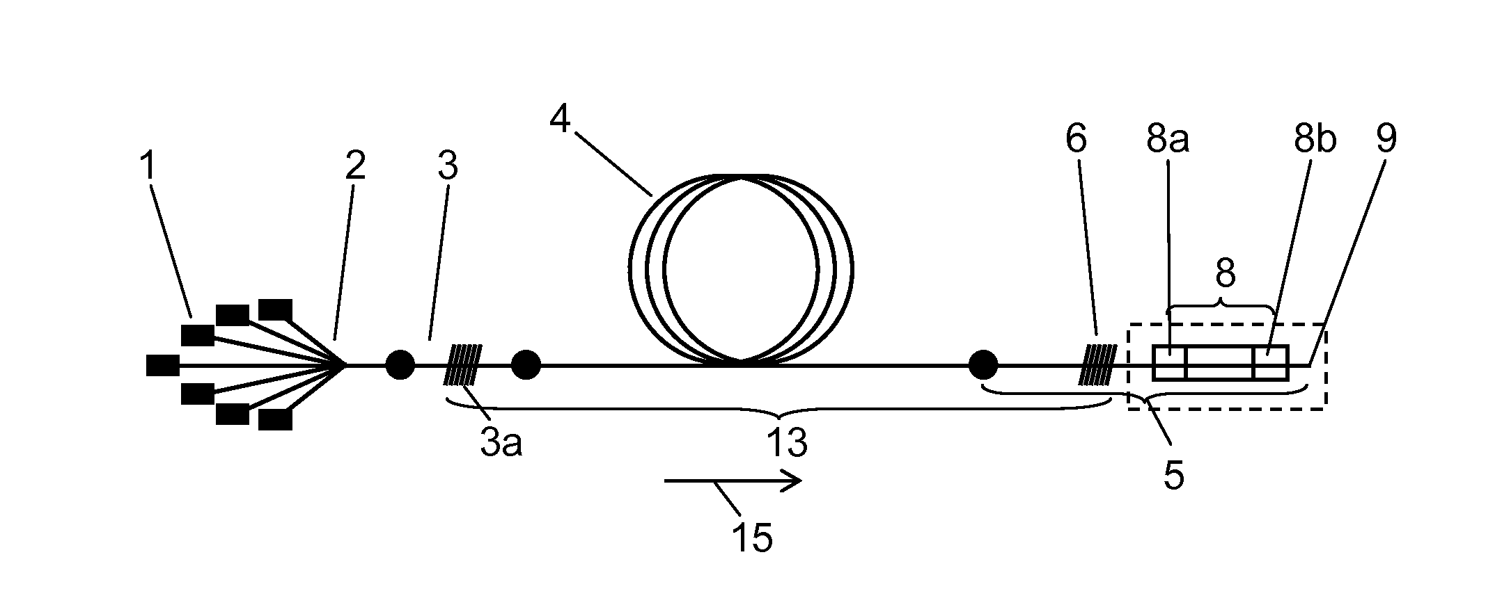
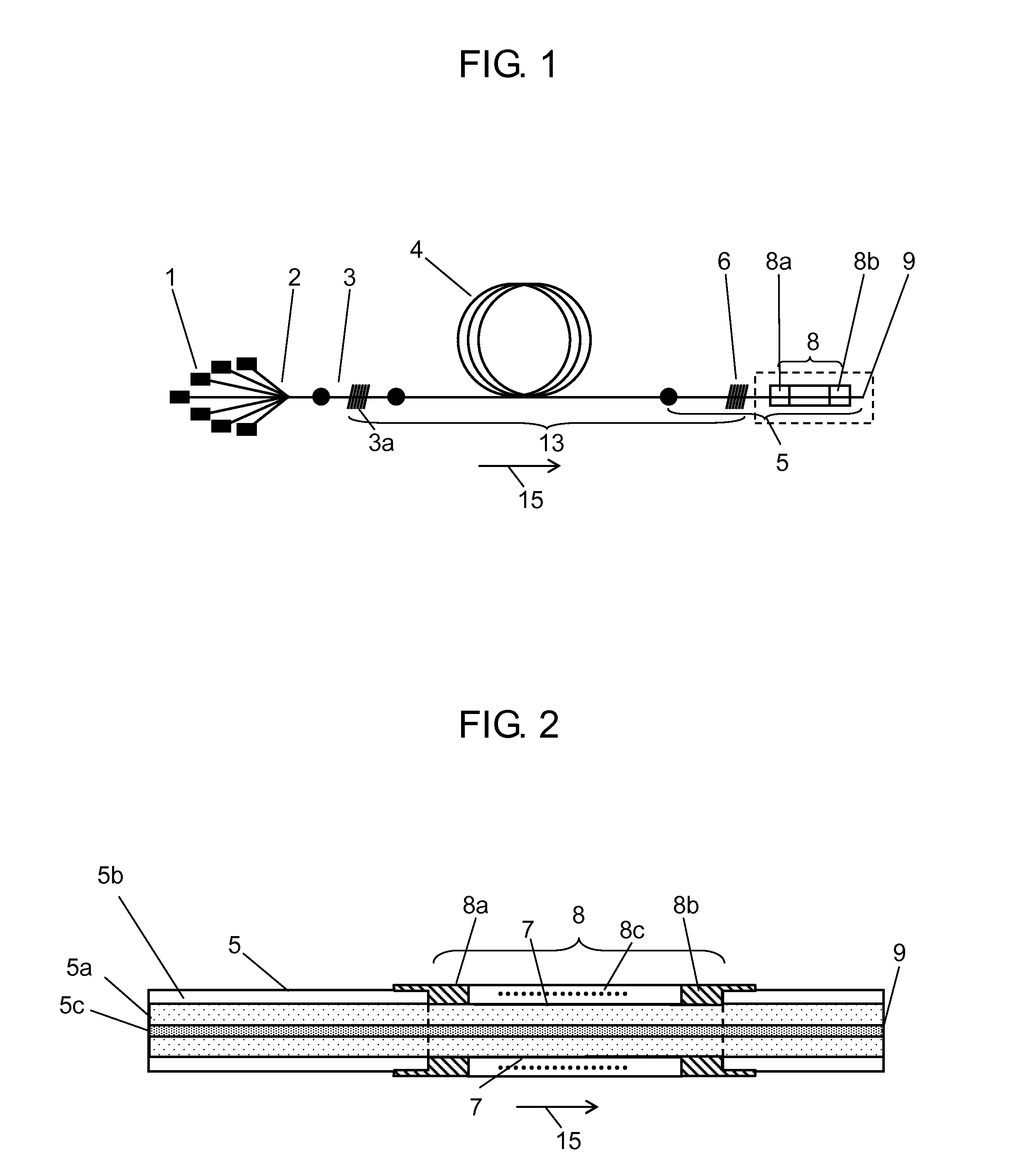
[0024]FIG. 1 illustrates the structure (including the high refractive-index resin coat structure), which generally shows from the oscillator to the resin recoated section, of a fiber laser in accordance with the first exemplary embodiment of the present invention. FIG. 2 shows a detailed structure of the high refractive-index resin coat section of the fiber laser in accordance with the first exemplary embodiment of the present invention.

[0025]As shown in FIG. 1 and FIG. 2, the fiber laser of the first exemplary embodiment has laser diode 1 for excitation, excitation light coupler 2, input double-clad fiber 3, oscillation double-clad fiber 4, output double-clad fiber 5, low-reflection FBG (fiber bragg grating) 6, second clad removed section 7, high refractive-index resin coat section 8, and output end 9 for oscillation light. Input double-clad fiber 3 contains a bragg diffraction grating as high-reflection FBG 3a, which is formed in core 5c of the fiber. Oscillation double-clad fiber...

example 1

[0049]Hereinafter, a specific example of the present invention will be described in detail.

[0050]As for laser diode 1, 19 single emitter laser diodes were employed (where, each diode offers 915 nm of center wavelength of output light and standard output of 12 W). A taper bundle fiber coupler in which 19-fiber-bundled quarts fiber (NA=0.15) provides output to a single-line fiber (NA=0.46) was employed for excitation light coupler 2.

[0051]As for oscillation double-clad fiber 4, a double-clad fiber having a single-mode core doped with Ytteribium (Yb) as a rare earth element was employed. Input double-clad fiber 3 having high-reflection FBG 3a therein and output double-clad fiber 5 having low-reflection FBG 6 therein were fusion spliced to each end of oscillation double-clad fiber 4 to form a fiber laser oscillator. In the fiber laser oscillator, FBG 3a and FBG 6 serve as a reflection mirror each other.

[0052]A resin having a refractive index of 1.38 was used for second clad 5b of double...


PUM


Abstract

The optical fiber of the present invention has an input double-clad fiber containing high-reflection FBG, an oscillation double-clad fiber, and an output double-clad fiber containing low-reflection FBG. The output double-clad fiber is formed of a core, a first clad, and a second clad. In the output double-clad fiber, a high refractive-index resin coat section recoated with high refractive-index resin whose refractive index is the same as that of the second clad or greater is disposed at a part where the second clad is partly removed between an output end and the low-reflection FBG. The refractive index of the high refractive-index resin coat section gradually increases along the direction in which light travels through the first clad.

Description

BACKGROUND[0001]This application is a U.S. National Phase Application of PCT International Application PCT / JP2012 / 003875 filed on Jun. 14, 2012, which claims priority to Japanese Patent Application No. 2011-144023 filed on Jun. 29, 2011. The disclosures of these applications including the specifications, the drawings, and the claims are hereby incorporated by reference in its entirety.[0002]1. Technical Field[0003]The present invention relates to fiber lasers using double-clad fibers, in particular, relates to the structure of a fiber laser capable of removing residual excitation light as unwanted light that is fed together with oscillation light from an optical fiber oscillator.[0004]2. Background Art[0005]For removing residual excitation light in double-clad fibers of a fiber laser, the following related arts have conventionally been suggested.[0006]According to the first one of the related arts, an optical fiber protecting body is provided to protect a fusion splice at which the ...

Claims


Application Information

Patent Timeline
IPC IPC(8): H01S5/14
CPCH01S5/146H01S3/06704H01S3/06733H01S3/0675H01S3/0804H01S3/09415H01S3/0401G02B6/02104H01S3/067H01S3/06708H01S3/06716H01S3/06745H01S3/0933H01S3/094003H01S3/094007
Inventor NISHIMURA, HITOSHIITOH, HIDEAKI
Owner PANASONIC CORP
Why Eureka
Try Eureka